
Example PWM generation
This page: what does the configuration look like for my board, specifically regarding PWM.
Make sure you have set up Ethernet according to the following page FIRST: Introduction and initial setup of embedded ethernet
PWM
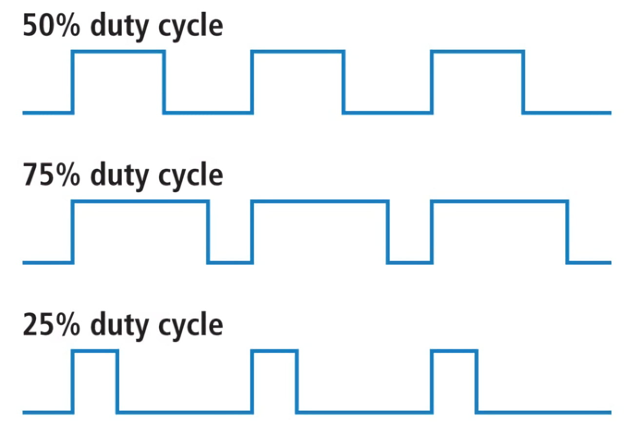
Pulse Width Modulation (PWM) is a technique for generating a continuous HIGH/LOW alternating digital signal and programmatically controlling its pulse width and frequency. Certain loads like (LEDs, Motors, etc) will respond to the average voltage of the signal which gets higher as the PWM signal’s pulse width is increased. This technique is widely used in embedded systems to control LEDs brightness, motor speed, and other applications.
> DeepblueMbedded.com
On the embedded subteam, we use PWM to control the motors for the Robotic arm and Drive system. In the world of PWM, two metrics are most important: duty cycle and frequency. The duty cycle is determined by the percentage of high/low signal, for example a 75% duty cycle means that the signal is HIGH 75% of the time. How long this total time is, is determined by the frequency. The frequency is to determine motor speed.
CubeMX
Make sure you have set up Ethernet according to the following page FIRST: Introduction and initial setup of embedded ethernet
1) Setting Pins
The only pin that is set at the moment (except for defaults) is PA0. It is set to TIM2_CH1, this means it uses Timer 2 Channel 1 for something, in this case it is PWM generation.
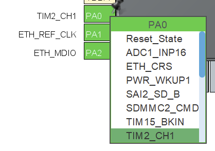
If we want to set more pins to generate PWM signals, we can use a workflow similar to what will be described below. Of course, you will need to choose a separate timer for each pin. Also make sure that the pin is suitable for PWM!
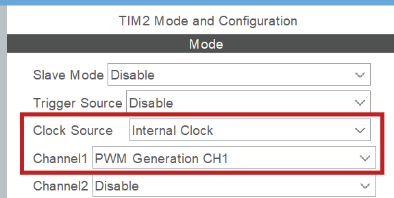
TIM2 > Mode
After you have set the pin, you need to enable the timer and channel to do something. We set Clock Source: Internal Clock to enable the timer and Channel1: PWM Generation CH1 to use PWM on pin PA0.
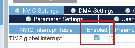
TIM2 > Configuration > NVIC settings
Enable global interrupt.
TIM2 > Configuration > Parameter settings > Counter settings
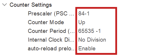
NOTE: -1 for prescaler and counter period because of 0 index counting
To fully configure the PWM generation, we have to set the above parameters. The prescaler has to do with the clock configuration. You want to set the prescaler equal to the amount of MHz in the clock configuration, because we will divide the clock frequency by the prescaler! Here, we have set the clock speed to 84 MHz (see Clock configuration), so we set the prescaler to 84 (-1) as well. This way we work with 1MHz in calculating the counter period for the wished for PWM frequency (see below).

NOTE: the counter period parameter uses the ARR (AutoReload Register). Those terms are used interchangeably in online sources.
As of now, the counter period is at 65535, which is the maximum value for an unsigned 16bit integer. This results in a PWM frequency of 1098Hz. The frequency of PWM should be suitable for the motor you are using. We can change this value later. For more information on PWM see resource 1.
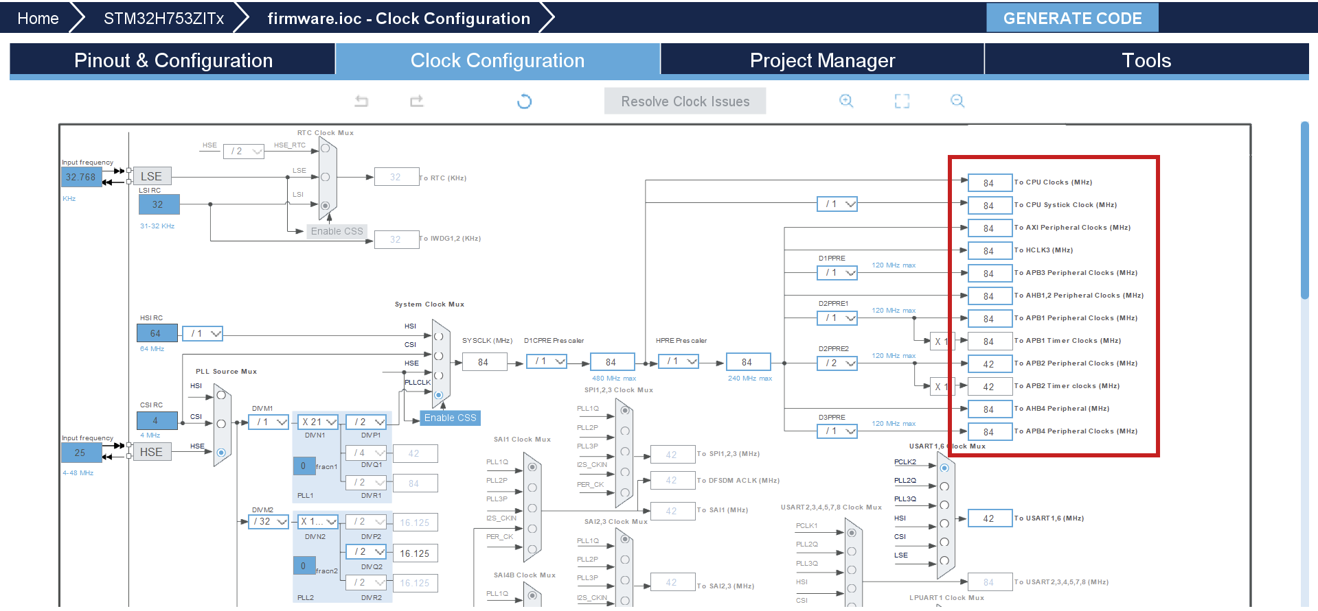
2) Clock configuration
The board can be optimized to run at a higher frequency than is preconfigured. You can set the system clock to work at 84 MHz by setting any of the right-hand clocks in the clock configuration menu to 84. The program then auto calculates the settings for the system, also see resource 2.
No comments to display
No comments to display