Make sure you have set up Ethernet according to the following page **FIRST**: [Introduction and initial setup of embedded ethernet](https://bookstack.roboteamtwente.nl/books/communication-system/page/setup-of-embedded-ethernet "Introduction and initial setup of embedded ethernet")
--- ## **PWM** > **Pulse Width Modulation** (PWM) is a technique for generating a continuous HIGH/LOW alternating digital signal and programmatically controlling its pulse width and frequency. Certain loads like (LEDs, Motors, etc) will respond to the **average voltage** of the signal which gets higher as the PWM signal’s pulse width is increased. This technique is widely used in embedded systems to control LEDs brightness, motor speed, and other applications. > > [DeepblueMbedded.com](https://deepbluembedded.com/stm32-pwm-example-timer-pwm-mode-tutorial/) On the embedded subteam, we use PWM to control the motors for the Robotic arm and [Drive system](https://bookstack.roboteamtwente.nl/books/drive-system "Drive system"). In the world of PWM, two metrics are most important: **duty cycle** and **frequency**. The duty cycle is determined by the percentage of high/low signal, for example a 75% duty cycle means that the signal is HIGH 75% of the time. How long this total time is, is determined by the frequency. The frequency is to determine motor speed. [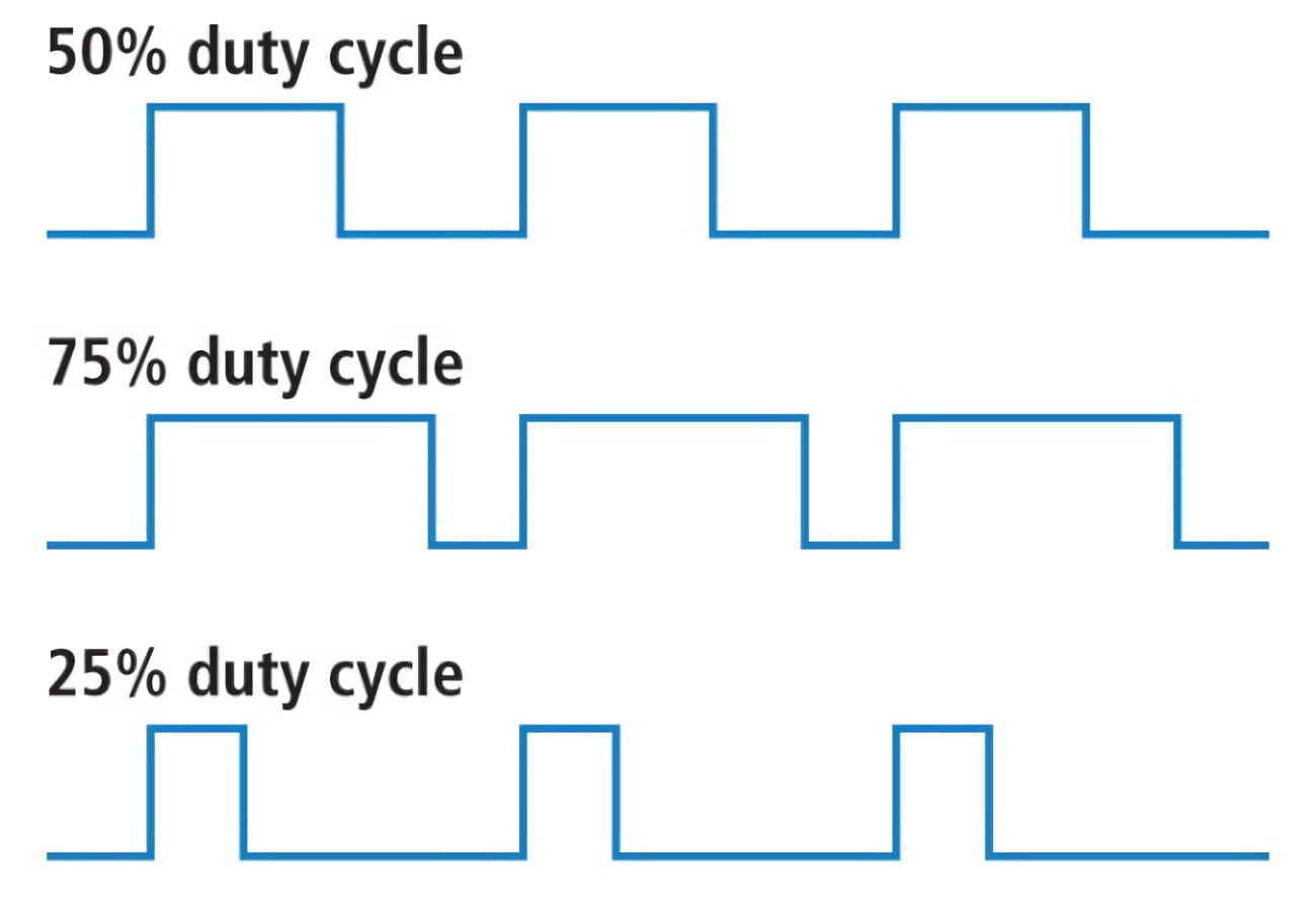](https://bookstack.roboteamtwente.nl/uploads/images/gallery/2026-04/NaAafbeelding.png) --- ## **CubeMX**Make sure you have set up Ethernet according to the following page **FIRST**: [Introduction and initial setup of embedded ethernet](https://bookstack.roboteamtwente.nl/books/communication-system/page/setup-of-embedded-ethernet "Introduction and initial setup of embedded ethernet")
### 1) Setting Pins The only pin that is set at the moment (except for defaults) is **PA0**. It is set to TIM2\_CH1, this means it uses Timer 2 Channel 1 for something, in this case it is PWM generation. [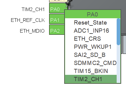](https://bookstack.roboteamtwente.nl/uploads/images/gallery/2026-04/ze1afbeelding.png) If we want to set more pins to generate PWM signals, we can use a workflow similar to what will be described below. Of course, you will need to choose a **separate timer** for each pin. Also make sure that the pin is **suitable** for PWM! ##### **TIM2 > Mode** After you have set the pin, you need to enable the timer and channel to do something. We set `Clock Source: Internal Clock` to enable the timer and `Channel1: PWM Generation CH1 `to use PWM on pin PA0. [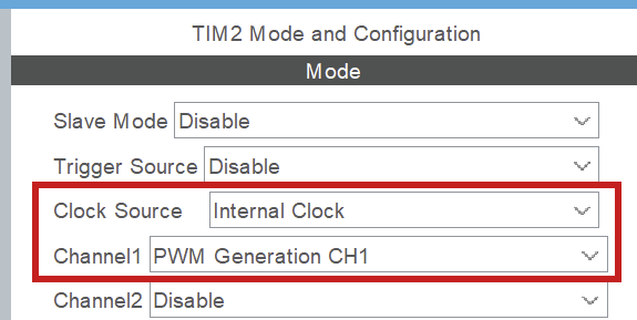](https://bookstack.roboteamtwente.nl/uploads/images/gallery/2026-04/a8Xafbeelding.png) ##### **TIM2 > Configuration > NVIC settings** Enable global interrupt. [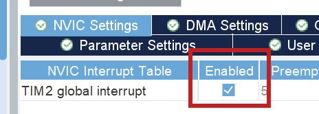](https://bookstack.roboteamtwente.nl/uploads/images/gallery/2026-04/phDafbeelding.png) ##### **TIM2 > Configuration > Parameter settings > Counter settings** [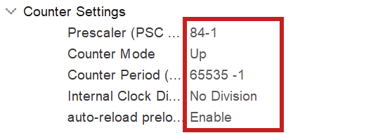](https://bookstack.roboteamtwente.nl/uploads/images/gallery/2026-04/lTKafbeelding.png)**NOTE:** -1 for prescaler and counter period because of 0 index counting
To fully configure the PWM generation, we have to set the above parameters. The **prescaler** has to do with the clock configuration. You want to set the prescaler **equal to the amount of MHz in the clock configuration**, because we will divide the clock frequency by the prescaler! Here, we have set the **clock speed to 84 MHz** (see [Clock configuration](#bkmrk-clock-configuration "Clock configuration")), so we set the prescaler to 84 (-1) as well. This way we work with **1MHz** in calculating the counter period for the wished for PWM frequency (see below). [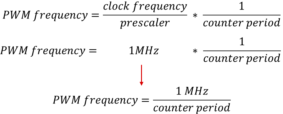](https://bookstack.roboteamtwente.nl/uploads/images/gallery/2026-04/xC5afbeelding.png)**NOTE:** the counter period parameter uses the ARR (AutoReload Register). Those terms are used interchangeably in online sources.
As of now, the counter period is at **65535**, which is the maximum value for an unsigned 16bit integer. This results in a PWM frequency of 1098Hz. The **frequency** of PWM should be suitable for the motor you are using. We can change this value later. For more information on PWM see [resource 1](https://deepbluembedded.com/stm32-pwm-example-timer-pwm-mode-tutorial/). ### 2) Clock configuration The board can be optimized to run at a higher frequency than is preconfigured. You can set the system clock to work at **84 MHz** by setting any of the right-hand clocks in the clock configuration menu to 84. The program then auto calculates the settings for the system, also see [resource 2](https://youtu.be/zHWvFchXhvw?si=nGj-vzkVCszjHonW). [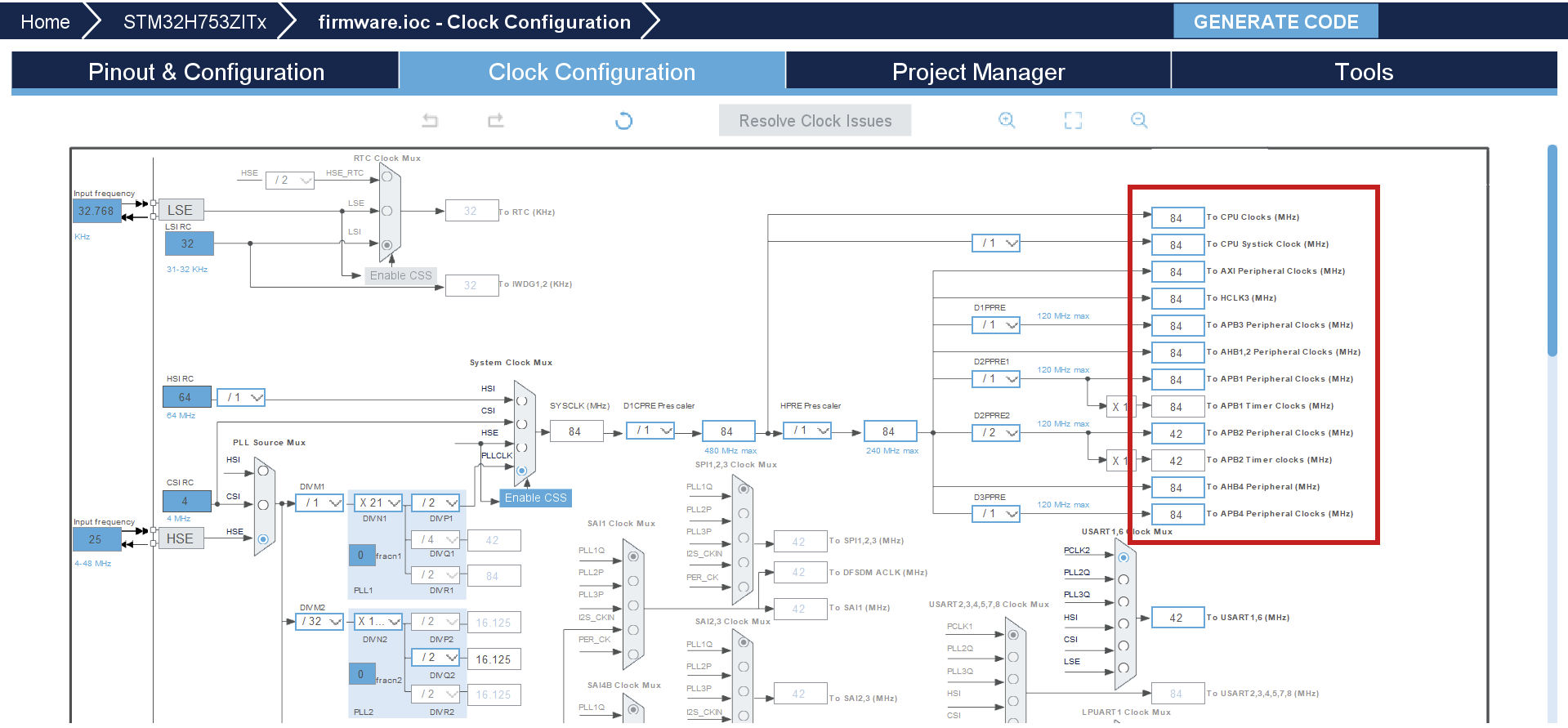](https://bookstack.roboteamtwente.nl/uploads/images/gallery/2026-04/oysafbeelding.png) --- ## **Resources** 1. [Deepbluembedded.com: STM32 PWM Output Example Code (PWM Generation Tutorial)](https://deepbluembedded.com/stm32-pwm-example-timer-pwm-mode-tutorial/) 2. [YouTube: STM32 Beginners Guide Part3: PWM, TIMERS, Frequency and Duty Cycle. LED Dimming with PWM example.](https://youtu.be/zHWvFchXhvw?si=nGj-vzkVCszjHonW)