
Automatic control
Overview
In general, the job of the control system is to turn high level instructions from the software system, and turn them into instructions for the hardware. This is done by having a positions in 3d space (x, y z), a final gripper angle (respective to the ground), controls for the rotation, controls for opening and closing the gripper, and a deltaTime as an input, and turning those into control signals for the motors:
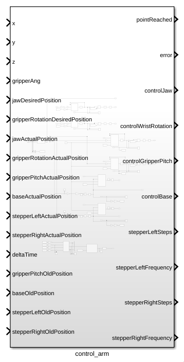
The control system also has feedback from the motors with variables with a name ending with ActualPosition, and the old positions of the motors, representing the position of the motors before the movement starts.
The movement starts whenever the input variables are changed, the old positions must come from an external source, and stay constant throughout the movement.
Inverse kinematics
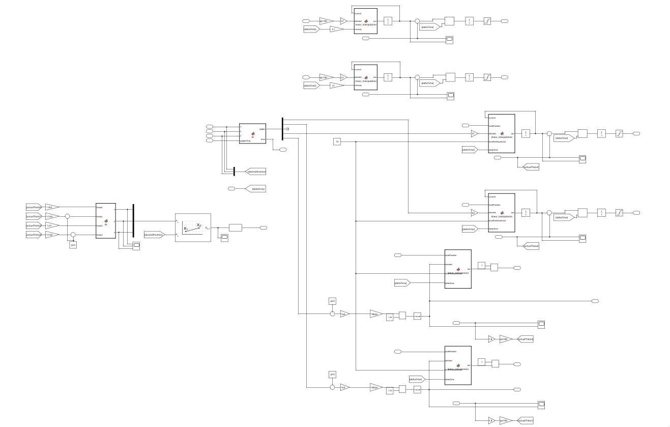
Starting of the process is the inverse kinematics, which is a matlab function block that calculates the necessary angles that the joints need to make given a final position.
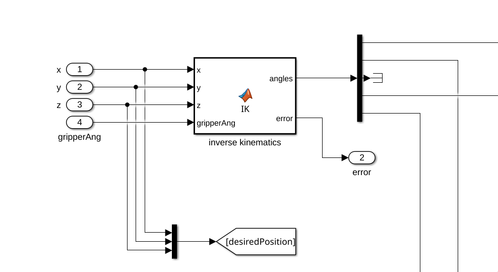
More information about how the inverse kinematics are done can be found in Kinematics.
After that, angles will be sent to the different motor control systems, where they will be processes as a desired position.
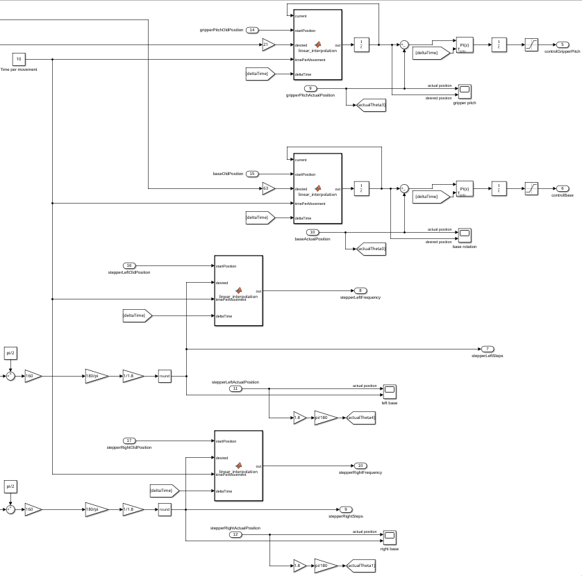
Here you will find a Time per movement constant, that will determine the speed at which a movement will be made. This is necessary to allow the motors to finish a movement at the same time, to minimize positioning issues.
Control signals
DC motors
The controllers used for DC motor control use a matlab function to linearly interpolate the movement, to allow for a smooth movement. It uses a start position, end position, and current position do determine how fast the motor should move.
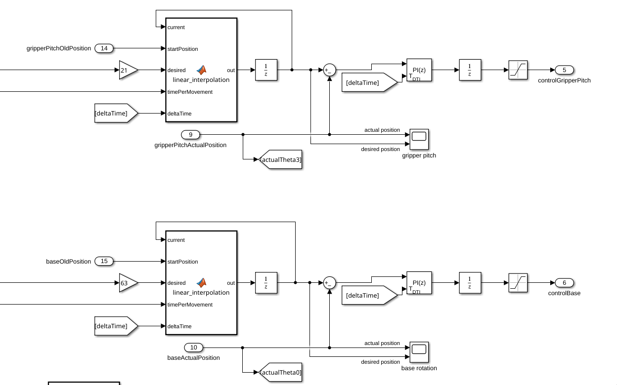
The gain blocks going into the desired inputs are used to take into account the gearboxes attached to these motors (21:1 gear ratio means move 21 times further).
After the linear interpolation, the motor will be controlled using simple PI controllers, using the actual position from the encoders as control input. The actual positions will also be used for forward kinematics later, so they are sent to goto statements.
The linear interpolation works like this:
function out = linear_interpolation(current, startPosition, desired, timePerMovement, deltaTime)

velocity = abs(desired - startPosition) / timePerMovement;

if current < desired
    current = current + (velocity * deltaTime);
end
if current > desired
    current = current - (velocity * deltaTime);
end

out = current;
The motors not used for positioning of the gripper (gripper rotation and jaw control) are also controlled using a linearly interpolated signal, but the velocity of these movements can be varied much more, because they are not dependent on the movement of the rest of the arm.
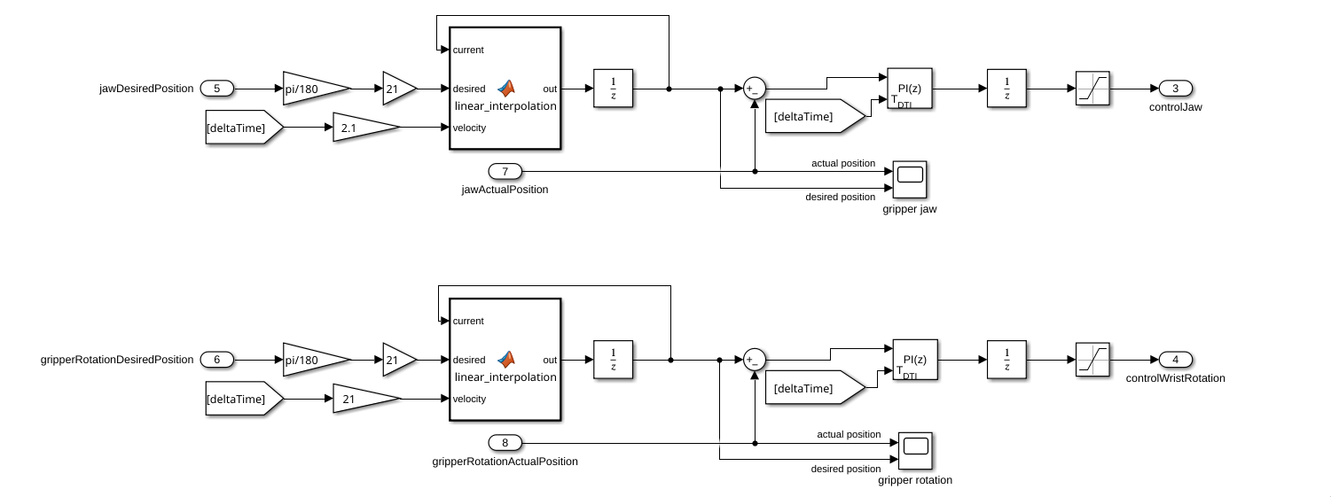
After the linear interpolation, the motors are controlled with PI controllers.
The gain blocks in front of the desired position are scaled to account for an input of degrees, and to account for the gear ratios of the motors. The velocities were arbitrarily picked.
The linear interpolation block works like this:
function out = linear_interpolation(current, desired, velocity)
if current < desired
    current = current + velocity;
end
if current > desired
    current = current - velocity;
end

out = current;
Stepper motors
The stepper motor control works fairly similar, but instead of sending control signals with a PI controller, it just sends the absolute position in terms of steps and the frequency at which the PWM signal should pulse.
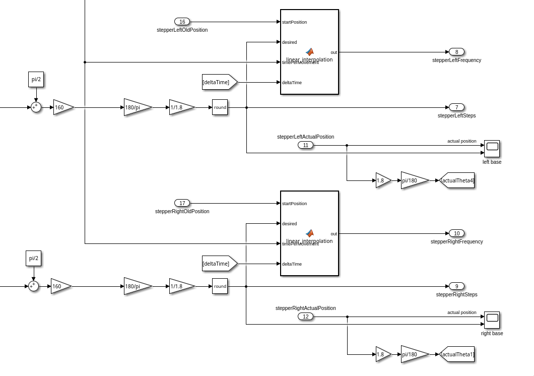
Before getting the desired position though, three gain block are used beforehand, to convert the angle gotten from the inverse kinematics to the position the motor should go to. In this process a, pi/2 gets added to the angle because of how they are calculated.
The gain blocks are here for this reason: 160 is because of the gear ratio between the motor and the actual movement, 180/pi is to convert from radians to degrees, and 1/1.8 is to convert from degrees to steps (these could have been one gain block, but it is more clear why they are here like this).
The frequency calculating function block works like this:
function out = linear_interpolation(startPosition, desired, timePerMovement, deltaTime)

velocity = abs(desired - startPosition) / timePerMovement;

out = velocity;
To confirm the robotic arm has reached the final position it has to, a forward kinematics function is used to get the projected position, which is then compared to the desired position.
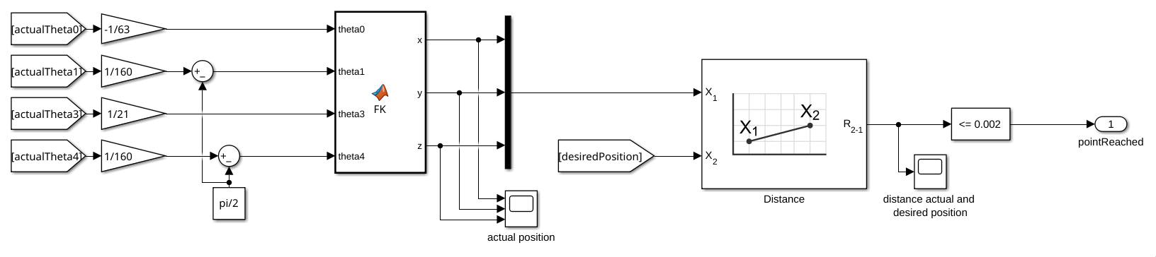
It does forward kinematics on the read values from the encoders, for that reason they have been scaled down to account for the gear ratios (pi/2 is subtracted from theta1 and theta4 because how the encoders are calibrated).
More on how the forward kinematics actually works in Kinematics.
No comments to display
No comments to display