
Simulation
Simulation of the drive system
Simulink
Overview
The simulation is done using a main control block called control_drive, which as inputs gets a turning radius, a distance to goal, and a deltaTime. From these inputs, different control signals are calculated for the different motors, using simulated DC motors as well as stepper motors. Both the types of motors send the relevant feedback to the control block using goto blocks.
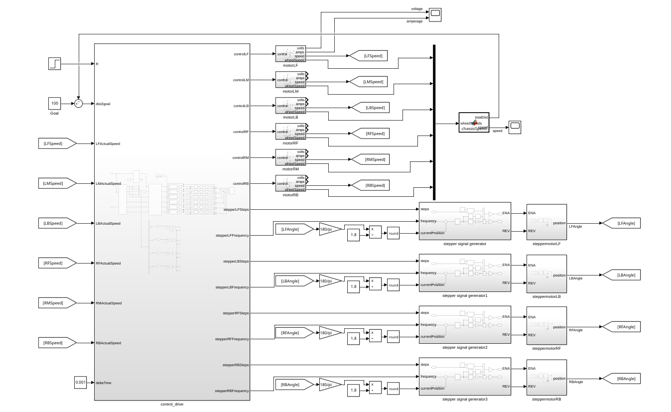
The driving motors are connected directly to the control block, processing the control signal directly.
The steering motors are connected to pulse generators to send instructions.
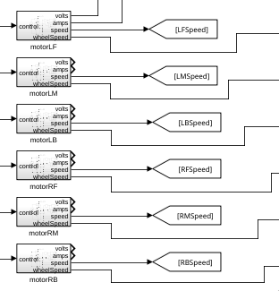
Driving motors
The driving motors are simulated as 6 motor blocks that have a control signal as input, and as outputs a speed from the motor, speed from the wheel, motor voltage and amperage.
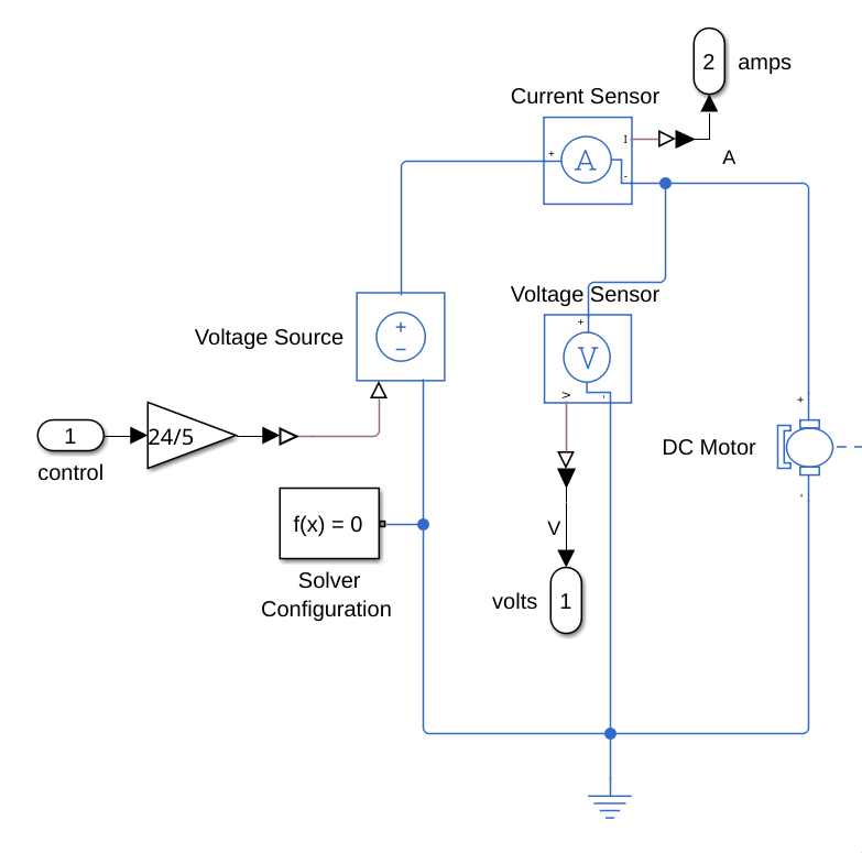
The driving motors are simulated with Simscape components, at first using a gain block with a 24/5 gain to what the motor driver would be doing (turning a 0V-5V signal to a 0V-24V signal). This value is sent to Voltage Source, which sends sends a voltage to a DC motor to create a rotational force.
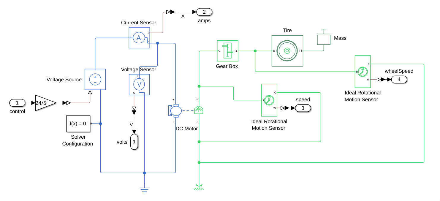
This voltage is also read by a voltage and current sensor to get the expected power values at different speeds.
The speed of rotation is measured both before, and after the connection to the gearbox:
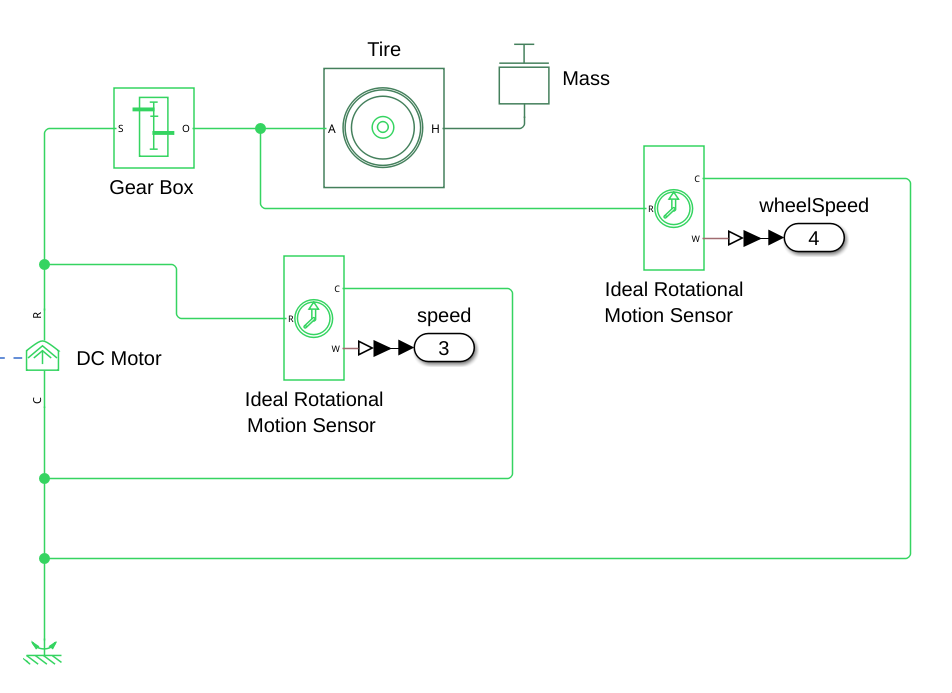
This is to get both the speed that would be read by the hall-sensors in the actual motors, as well as the speed going to the wheels to do further calculations with. The rotation of the motor after the gearbox is also connected to a tire with a mass equal to 1/6th of the mass of the rover.
Six of these motors are simulated, with the motor speed being used as feedback for the control system, and the wheel speed being used to calculate the actual speed of the rover.
Steering motors
The steering motors are connected to the control by connecting them to pulse generators that send signals to the stepper motors to set them to the correct positions.
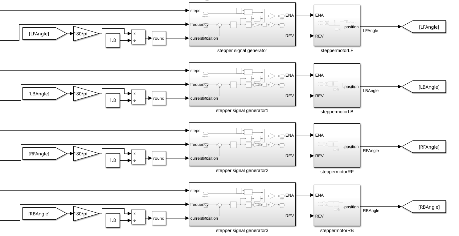
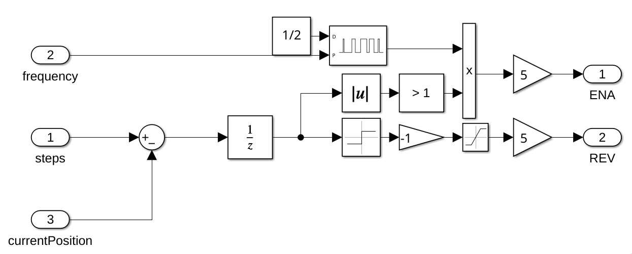
The calculation before the current position enters the signal generator is used to convert the motor angle from radians to stepper motor steps. This is done to be able to control the stepper motors with the amount of steps that have been/ need to be taken to get to a certain position.
The stepper motor blocks themselves contain a simple stepper motor with a stepper motor driver, reading the final angle the motor moved to as output.
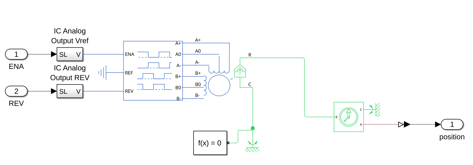
To control the motors, an ENA and REV signal are sent from pulse generator blocks (REV specifies the direction that the motor spins and ENA is a pulse signal activating the steps):
This is done to simulate the behaviour of the PWM signals that will be sent by the STM32 microcontroller.
No comments to display
No comments to display