
Parallel Linkage
1. Requirements
The structure of the robotic arm is the connection point between the rover and the end-manipulator. Hence, it is crucial to aim for a large reach and a lightweight dynamic structure that can support the loaded gripper and allow for precise motion. During the academic year 2025-2026, the aim was to develop Before starting the design phase, a list of requirements was set:
(a) The robotic arm shall reach a distance of around 1 meter when fully extended in any direction.
(b) The robotic arm shall aim for an overall lightweight design (less than 10kg)
(c) The robotic arm shall be easy to mount on the rover (5-10 minutes mounting time)
(d) The robotic arm shall be easy to disassemble (<30 minutes)
(e) The robotic arm shall be easy to assemble (<30 minutes)
(f) The mounting of all actuators shall consider cable management.
(g) Off-the-shelf components are prioritised during design and assembly
(h) The manufacturing of all parts shall be possible within the university infrastructures
2. Concept & Motivation
A parallel linkage was chosen as the structure of the robotic arm for weight reduction purposes. During early design phases, it was observed that the shoulder motor (see Figure 1) would require significantly higher torque requirements to handle the rest of the arm. These high torque requirements are induced by the considerable length of the robotic arm (aiming for a reach of around 1 m) but also because of the weight created by the elbow motor that results in a significant increase in inertia.
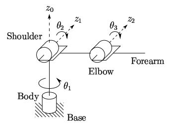
Figure 1: Kinematic diagram of traditional robotic arms and joint names [1].
To address these challenges, we opted to utilise a parallel linkage for the robotic arm's structure (see Figure 2). This structure groups the 2DOFs (θ2 and θ3) at the base of the linkage, minimising the inertia of the entire robotic arm. The disadvantages of this structure include a reduced reach, as it is physically challenging to extend the arm fully, but also a less instinctive arm design that might result in control challenges. After evaluating all factors influencing the design (motor selection, design components and manufacturing), it was decided that the parallel linkage remains an interesting trade-off for the whole system and hence was selected as the final concept.
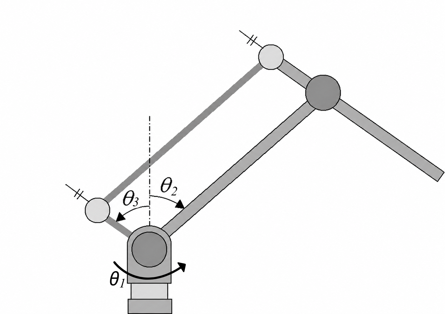 Figure 2: Kinematic diagram of parallel linkage [2].
3. Design & Materials
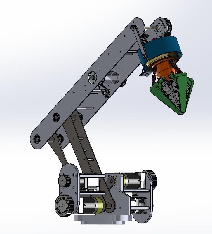
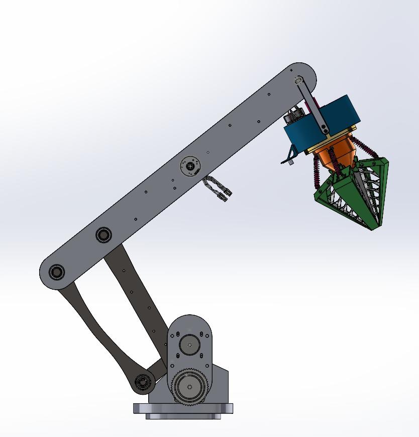
Figure 3 shows the final execution of the parallel linkage concept presented in the last section. A 3D-printed circular base is used as a connection point with the Base assembly. Four 3D-printed vertical plates are used to mount the two motors and gearboxes that actuate the two shoulder actuations (θ2 and θ3). The wrist actuation of the end-manipulator (moving the gripper up and down, see the Gripper page) uses a DC motor located in the middle of the forearm to reduce inertia and avoid mounting the gripper directly on the motor. A 1:1 belt drive transfers the torque from the DC motor to the gripper.
All plates used in the parallel linkage were laser-cut from 3 mm-thick aluminium sheets ordered from MCB Direct. All shafts that were not included in a motor or a gearbox were turned at CUBE, from raw material ordered from RS. Five deep-groove ball bearings were used to support all moving shafts within the parallel linkage (16101). All pulleys are 3D-printed due to manufacturing challenges to fit the gearbox and motor shafts. The belts were ordered from RS. The aluminium sheets are mounted and held together by standoffs from RS. This structure is called a 'sandwich'. The top sandwich (or forearm) uses a combination of two M4 standoffs (50 mm and 60 mm) to reach a size of 110mm. The bottom sandwich uses M4x40 mm standoffs.
spacespacespacespacespa(a)spacespacespacespacespacespacespacespacespacespace (b)
Figure 3: Full assembly of the parallel linkage, where (a) shows the connections with the shoulder motor and gearboxes, the integration of the wrist motor, and the connection to the gripper, and (b) shows the side view of the assembly, where the final design of the parallel linkage is clearly visible.
The stepper motors (ST5918M3008-B) and gearboxes (GPLE60-3S-80) actuating the shoulder DOFs are from Nanotec. Additionally, the stepper motors were ordered with an additional encoder (NTO3-05-C06 (6.35 mm)) and brake (BRAKE-BCD56-1,5-8). The wrist motor (AK45-10) was bought from CubeMars.
References:
[1] Gupta, Ayush & Chourika, Sameer & Agrawal, Sankalp & Deshmukh, Ankur & Bhargava, Prasham. (2018). A Geometric Approach to Inverse Kinematics of a 3 DOF Robotic Arm.
[2] Ahn, Kuk‐Hyun et al. “Reduction in gravitational torques of an industrial robot equipped with 2 DOF passive counterbalance mechanisms.” 2016 IEEE/RSJ International Conference on Intelligent Robots and Systems (IROS) (2016): 4344-4349.
No comments to display
No comments to display