Drive System
Drive System
Driving Motors (cubemars)CubeMars)
Each of the 6 driving motors need torequires power and data (CAN and UART) routed from inside the chassis of the rover.
Power
Power is donedelivered over a black (–) and a red (+) wire. ItThese runswires run through the insideinterior of the aluminum extrusions and terminatesterminate in a female xt-XT-60 connector.connector Theat each of the wheels.
Each motor is connectedconnects to thethis system withvia a shortershort power cable whichwith:
- Male
maleXT-30xt-30on(whichone end — plugs into themotor)motor - Male
toXT-60maleonxt-60the(whichother end — plugs into therover).rover's female XT-60 connector
Data
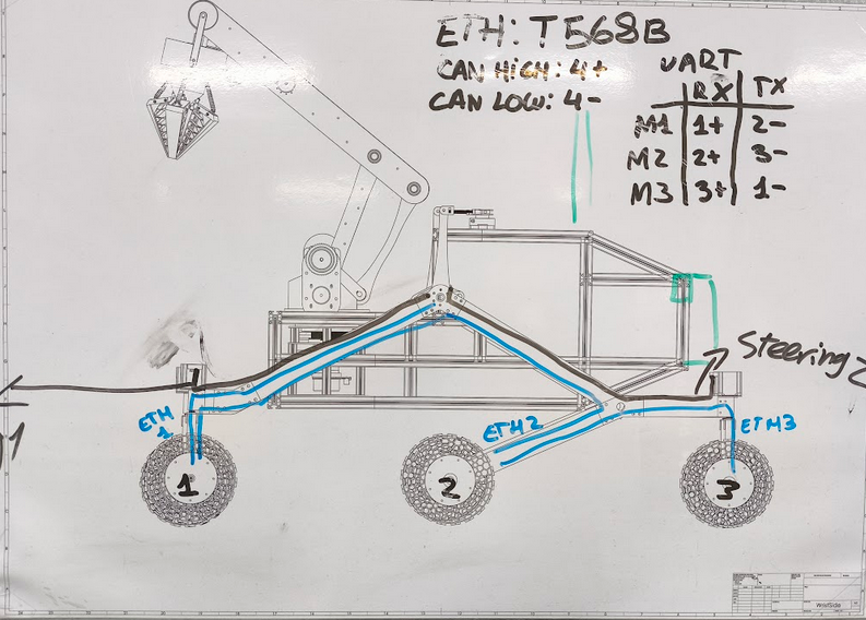
Data is donecarried over Ethernet cables and connectors.connectors, Wewired are followingto the standardT568B T568B.standard.
Each wheel has one ethernet-Ethernet-in and one ethernet-out,Ethernet-out withconnector, the exception ofexcept the back wheelswheels, which have ehternet-an Ethernet-in and a terminator (a 120Ω resistor). Therein is a totalplace of Ethernet-out.
Motor numbering:
Position | Motor ID |
|---|---|
Front wheels | M1 |
Middle wheels | M2 |
Back wheels | M3 |
Cable layout (per side, 3 ethernet cables ontotal):
Cable | Run |
|---|---|
Cable 1 | Chassis |
Cable | Front wheel |
Cable | Middle wheel |
Ethernet Connector Pinouts
Each of the wheelswheel has two female ethernetEthernet connectors,connectors: one forin, one out. Pin assignments below follow T568B pairing (pins grouped by pair: 1–2, 3–6, 4–5, 7–8 in andstandard anotherEthernet, forbut out.here Theshown front wheels motors are M1, middle ones M2 andper the backrover's onescustom M3.signal The wiring for the female ethernet connectors is as follows:mapping).
M1 in– In
| + |
| |||
|---|---|---|---|---|---|
1 | RX | M1 out | |||
2 | M1 out 2+ | TX | |||
3 | M1 out 3+ | M1 out | |||
4 | CAN HIGH 1 | CAN LOW 1 |
M1 out– Out
| + |
| |||
|---|---|---|---|---|---|
1 |
| M1 in | |||
2 | M1 in 2+ |
| |||
3 | M1 in 3+ | M1 in | |||
4 | CAN HIGH 2 | CAN LOW 2 |
M2 in– In
| + |
| |||
|---|---|---|---|---|---|
1 | M2 out 1+ | M2 out | |||
2 | RX | M2 out | |||
3 | M2 out 3+ | TX | |||
4 | CAN HIGH 2 | CAN LOW 2 |
M2 out– Out
| + |
| |||
|---|---|---|---|---|---|
1 | M2 in 1+ | M2 in | |||
2 |
| M2 in | |||
3 | M2 in 3+ | ||||
|
|
|
M3 in
|
| |
|
| |
| ||
|
|
|
4 | CAN HIGH 3 | CAN LOW 3 |
M3 – In
Pin | + | – |
|---|---|---|
1 | — | TX |
2 | — | — |
3 | RX | — |
4 | CAN HIGH 3 | CAN LOW 3 |
Motor-Side Connection
The female ethernetEthernet connector cables are connectorconnect to the motors through gh-connectors.via GH connectors.
Warning: The ghGH-side sideconnector should never be disconnected from the motormotor. becauseThis connector sits inside the connector is in themotor driver and quiteis flimsy,physically flimsy — one ofdriver the drivers washas already been bricked from connectingbeing it and disconnecting itconnected/disconnected too muchmany times.
Steering motors
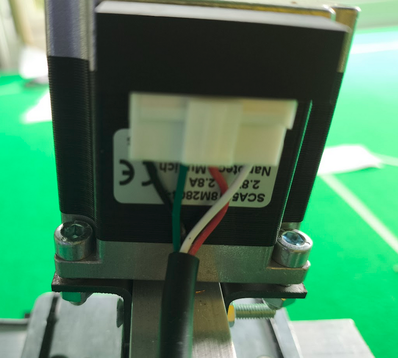
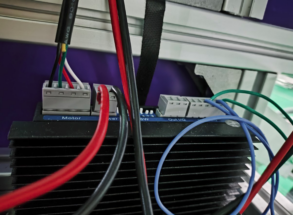
The steering motors are connected through 5-way wire (with one of the channels cut off) to the motor drivers.