
STM32CubeMX
This page: the short, concrete workflow for using STM32CubeMX to configure an STM32 project and generate init code without accidentally nuking your work.
Download: https://www.st.com/en/development-tools/stm32cubemx.html
1) What is it
STM32CubeMX is a graphical tool that simplifies the configuration of STM32 products, and generates the corresponding initialization code through a guided step-by-step process.
> st.com
In the embedded subteam, we use STM32 Nucleos to make our robot come to life. We use CubeMX to enable these boards to do what we want by setting the pins on the physical board and generating code that we can use to drive those pins.
2) Starting a (new) project
Once you have successfully installed CubeMX, you can either create or open a project. You will most likely be working with already existing CubeMX projects. You can open any project by finding the .ioc file. This is the configuration file for any CubeMX project.
However, there are some important settings that any project needs.
a. New project
When creating a NEW project make sure you use the board selector and NOT the MCU selector to start your project (given the fact that you will be working with a board). If you don't do this, it will cause problems down the line.
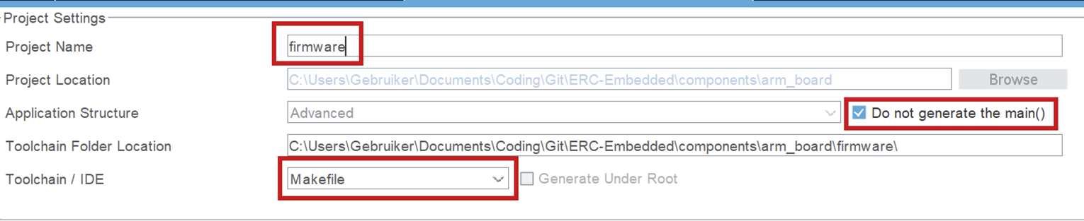
b. Project Settings
Project Manager > Project
Once you have your project open, navigate to the project manager.
- It is important that your project name is "firmware", since this is the name the folder is supposed to have in the embedded structure. (This is platformio configuration related.)
- Do not generate main(). You should only generate a main function to check what is in there and use it as an example, but when you want to build, you can not have a main function in your auto-generated code. It will conflict with your own main function.
- Set the toolchain to Makefile. You should not use another toolchain, because the post code generation script uses information from the Makefile!
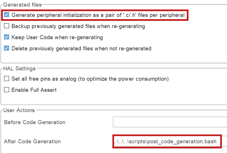
Project Manager > Code Generator
- Click the box to generate separate files per peripheral. Otherwise you will encounter errors surrounding missing libraries when building.
- Set the after code generation script. It can be found in
scripts/post_code_generation.bash. More information in Post-Generation Scripts.
NOTE for Windows users: the post generation script will NOT automatically be ran for you. Instead, you will have to run the script by hand in the git bash terminal.
3) Typical Workflow
a. Configure pins & peripherals
- In Pinout & Configuration: enable the peripherals you need (UART/SPI/I2C/CAN/Timers/ADC/etc.).
- Assign pins and resolve conflicts (CubeMX will warn you).
- Configure DMA + NVIC if needed (especially for high-rate IO or RTOS systems).
b. Set up the clocks
- Go to Clock Configuration and set your clock source (HSI/HSE) and PLL to the target system frequency.
- Verify peripheral clocks (UART baud rates and timer frequencies depend on this).
- If USB is used, make sure USB clock requirements are satisfied (CubeMX will usually flag invalid setups).
c. Code generation
Do not write custom code in CubeMX-generated files.
CubeMX will overwrite generated files during regeneration. Any custom code placed there will be lost, even if it appears to work temporarily.
Rule:
- Generated code is read-only.
- Your code lives outside of it.
What to do instead:
- Put all application logic in your own source files (
src/, modules, drivers, etc.). - Only use generated code as initialization and hardware configuration.
- Call your own code from the appropriate entry points (e.g. after init in
main()).
Bottom line:
If your code depends on surviving a “Generate Code” click, it’s in the wrong place.
d. Generate code, then build & verify
- Open Project Manager and confirm the project type/toolchain and output path are correct.
- Click Generate Code.
- Immediately review changes (e.g.
git diff). If CubeMX changed a lot more than expected, stop and investigate before committing. - Build the firmware and run a basic smoke test (UART prints, LED blink, peripheral init success, etc.)
No comments to display
No comments to display