
Wheels and Wheel Hubs
Overview & Design Intent
The rover uses a non-pneumatic, cellular wheel design. The goal of this was to provide compliant deflection, passive damping, and terrain conformity without the risk of punctures or pressure loss. While technically these wheels would not be feasable on the martian surface due to temperature fluctuations and radiation, these wheels will be fine since the competition takes place on earth.
The deep dive into the engineering, geometry, and finite element method (FEM) optimization lives in the companion report: "Design and Development of a Rover Drivetrain". Check that document if you need to understand the structural load calculations or deformation simulations.
Requirements
- Primary Role: Provide ground traction, terrain conformity, and passive shock absorption for the drivetrain.
- Target Load: 12.5kg per wheel
- Outer Diameter / Width: The diameter of 200mm was chosen due to the torque requirements in the worst case scenario being to high. The width was chosen to be 140mm because the original motor and gearbox combination that was supposed to be used with these wheels was that length.
Material Choices
- Outer Tire (TPU 95A): TPU 95A was chosen as it was flexible enough so that it woud not get damaged with hard impacts but also not too flexible like TPU90A which would have required more material for similar rigidity. This would have made the wheel heavier, increased its printing time, and increased its cost.
- Inner Hub: Currently the hubs consits of 3 differnet materials, PA6-CF20, Fiberon PETG rCF-08 and Polymax Polycarbonate. The first 2 were printed from PETG rCF-08 as that was the strongest filament on hand at that time. These were done at 100% infill, however this caused a problem known as the "blob of death". This is when the print nozzle slighlty collides with already printed lines, causing a buildup of matieral which if not stopped can cause the material to buildup all the way into the printhead wiring and if not carefully removed can cuase damage to the wiring which is a big annoyance to fix. So for the following hubs an infill of 80% was decided as that was the infill where no blob was seen.
The next 2 were printed from polycarbonate as the general idea was that these were stronger than the PETG rCF. While this is true in general, the specific verion of ploycarbonate (Polymax) from polymaker is generally weaker than other polycarbonates (Polylite) and even the PETG rCF. While it seems to have held up to this point, extensive stress tests have not been conducted in order to see their long term feasibility.
The final 2 where made from PA6-CF20. It is one of the strongest filaments offered by polymaker. It is very rigid and the best filament for this purpose as the entire rover's weight rests on the mounting points that connect the hubs to the plate that connects to the motor. In the future this should be used mainly for the hubs if the same design is kept, however other materials could suffice such as CoPA, Polylite PC, or others depending on the weight of the rover.
Manufacturing & Assembly Guide
All prints used OrcaSlicer's calssic wall generator instead of Arachne. While Arachne is quicker is does this by havig variable wall thicknesses. This can cause artifacts espcailly at small tight corners.
1. 3D Printing Settings
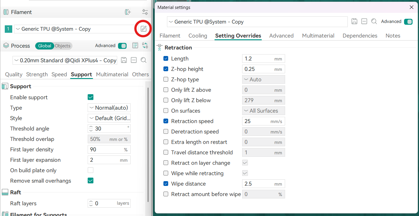
- TPU 95A Tire Settings: Due to TPU's flexibility printing with it can be quite a pain, however, OrcaSlicer's Generic TPU present is quite good. A few tweaks were made to the material settings in OrcaSlicer in order to mitigate the stringing which can cause the wheel to not only look ugly, but can affect tolerances. These settings can be tweaked further, but at the moment these seemed to balance stringing mitgation while not underextruding too much. The main changes were done to the retraction settings seen in the image below. An increase in the retraction length prevented material from oozing out the nozzle when we do not want it to. Retraction speed was put to 25mm/s as too quick of a retraction can cause the TPU to bend and tangle inside the extruder. Wipe distance is how far the nozzle will go back over the section it just printed before moving to the next section. This is to remove any material that oozed out the nozzle post retraction. Increasing this can reduce stringing, but can also increase printing time. Z-hop hieght was set to 0.25 as the layer height was set at 0.2 so the defualt of 0.4 was too high and increased printig time.
- PA6-CF20 Hub Settings: The present in OrcaSlicer is good for this. Has to be printed in the QiDi or similar that has an enclosed printing bed as this material likes to absorb moisture. Another requirement is that the printer needs to have a hardened nozzle as this material contains carbon fiber which is very abrasive (already installed as standard on the QiDi just make sure other printers obtained in the future has this as well). The material should also be kept in an enclosed box while printing as again, it absorbs moisture very easily.
2. Component Interfaces
- Tire-to-Hub Interface: The
- Hub-to-Gearbox Interface: asdsad
3. Maintenance & Lessons Learned
- Wear Indicators: asdsad
- Spares & Replacements: asdasdas