
Turning System
The turning system provides active steering for the front and rear wheel assemblies. To ensure high reliability during operation, the subsystem uses a direct-drive arrangement engineered to withstand heavy vertical static loads while eliminating mechanical play and plastic material deformation. It was desinged in a way to provide rotation while preventing vertial load transfer to the stepper motor as their axial load limit is much lower than the load of an individual turning system.
System Architecture & Components
The finalized design (Version 2) replaces indirect mechanical transmission with direct motor drive to simplify the assembly and maximize torque transfer efficiency.
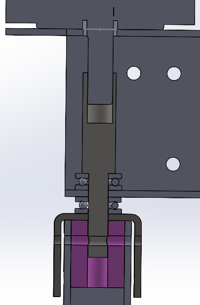
- Stepper Motor: Directly drives the steering shaft without intermediate reduction gears. This eliminates backlash, reduces total part count, and removes gear-tooth wear as a potential failure point.
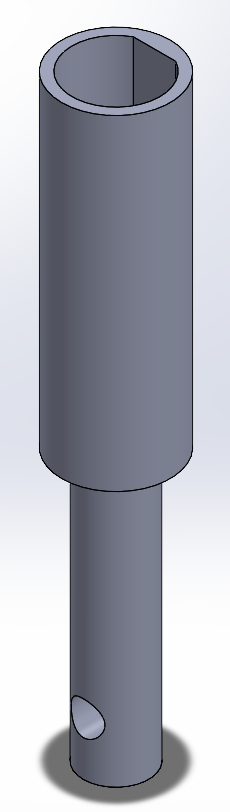
- Custom Interface Shaft: Machined shaft tapped at the side and secured to the stepper motor shaft via a set screw. It translates the rotational output of the motor shaft into a rigid mechanical connection for the turning core. It was designed in such a way that for some reason the interface shaft was pushed upwards it would not load the axial direction of the stepper motor shaft. (Note: In this image the set screw is not present as that was an addition made during manufaturing as the creation of D-bore with the chosen material was deemed not possible with the equiment at Cube.)
- Lower Core Block (Plastic Cube): Connected securely to the upper interface shaft it aids in a more even tranfer of torque form the shaft to the vertial square tubes, provides support for the screws connecting the U-shaped bracket to the vertical square tubes and interface shaft, and supports the U-shaped bracket in the center where the thrust bearing load is.
- Vertical Square Tubes: Act as the primary load-bearing rotating columns for both the front and rear steering assemblies. The vertial load is carried upwards with this tube and then trasnferred to the U-Bracket, which transfers it to the thrust bearings which then trasnfers it to the suspension system.
- U-Shaped Steel Brackets: Mounted to the exterior of the vertical square tubes. They provide a flat, rigid metal surface that prevents localized plastic crushing under heavy structural loads.
- Thrust Bearings: Positioned flush against the steel brackets. They isolate the vertical forces caused by the weight of the rover enabling smooth rotational motion under full payload.
Design Rationale
Version 1: The initial concept attempted to use a 3D-printed gear (30 mm diameter) driven by an M6 60 mm bolt and hex nuts pressed into embedded cutouts inside the plastic cube. This was was the first idea that came to mind when thinkning of not exceeding the axial load limit of the stepper motor.
- Primary Failure Mode 1 (Gear Shear): The main probelm foreseen with this concpet was that under high torque the gear could bend causing jumping/slipping whihc would not be ideal. Another probelm was the gear would degrade quite quickly.
- Primary Failure Mode 2 (Interface Stripping): High torque from the stepper motor concentrated immense torsional forces onto the sharp corners of the embedded hex nuts. Because plastic yields easily under point loads, the nuts quickly stripped out their plastic pockets, causing total loss of rotational control.
- Primary Failure Mode 3 (Nut loosening): Since the system relies on two nuts that are screwed into each other to create a lock; under high amounts of torque and continuous vibration, these nuts would eventually loosen making the turning system useless.
Version 2 (Current Production Design):
- Direct Drive Integration: Eliminating the printed gears entirely removed the primary shear risk. Driving the turning column directly ensures 100% torque transmission from the stepper motor without intermediate mechanical loss.
- Metal-on-Metal Fastening: Switching to a tapped metal interface block with set screws distributes clamping pressure evenly across the flat of the motor shaft. This prevents the rounding and stripping experienced in plastic cutouts.
- Axial Load Isolation via Thrust Bearings: Standard radial bearings or plain plastic bushings degrade quickly when subjected to heavy vertical loads down the steering axis. Placing thrust bearings against rigid U-shaped steel brackets creates a dedicated path for vertical forces to pass through the frame. This protects the internal stepper motor bearings from dynamic impacts during travel and maintains low rotational friction.
Failure Modes
The turning system is one of the more intrecate parts of the drive system, but in this case it was one of the more rushed systems as time was running out and the main focus was getting a subsystem that worked for now and could be improved on in the future.
- Failure Mode 1 (U-Shaped Bracket tolerancing): Since the U-shaped bracket relies on bending to create it, it sufferes from multiple steps that are quite inaccurate. One must first score the original plate, then line up the scored line by eye in the bending machine, and then bend the plate. This must be done for both sides as the machine can only do one side at a time. This process is very inaccurate and causes that the holes do not line up well, the dimensions to be off, etc. This is why in the current rover they do not exist. They were replaced with washers. This combined with other oversights caused quite some problems with the lower part of the suspension system.
- Failure Mode 2 (Interface shaft underconstraints): Currently the interface shaft only has one hole that connects the upper half of the suspension system to the lower part. Erm, yeah idk chief, I was kinda dumb ngl