Motor Subassembly
The drivetrain report details the original V1 concept. However, just 2–3 weeks before the qualification video deadline, the decision to change motor suppliers and therefore motors was made. V2 is an adaptation designed to integrate alternative motors on short notice while repurposing as many V1 hardware interfaces, adapter plates, and mounting geometries as possible. This ended up making the mouting interface between the motor and the hub quite a bit easier. The older motor had a long planeteray gearbox attached to it, which required a "cage" around the motor-gearbox combination to protect it from the spinning wheel surrounding it. This coupled with a singular point of attachemnt for the wheel requireing pre-loading on the pilot screw to prevent the screw from becoming undone during operation increased its complexity. The new motor is larger is an all in one motor/gearbox solution with 6 M3 mounting points. this made it drastically easier to mount.

1. Overview
- Primary Role: Provide a mounting point for the motor while also also protecting it from the spinning wheel surrounding it.
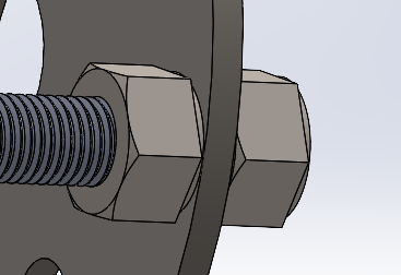
- Design Philosophy: Since the goal at the beginning of the year was to have every component be modular and easily replaceable it was quite tricky to come up with a nice solution. Therefore, six M8 threaded rods were chosen each cut at 140mm (currently cut to 110mm for the new motor). This was done as according to rough FEM simulations, when loaded, these six rods would only bend about 1-2mm. Keeping this displacement low meant that "squatting"or unwanted camber is mitigated. The plates, where the motor is mounted and where the subassembly is mounted to the suspension, are held inplace with nuts that are tightened into each other clamping the plate between them. While this is not the best solution, it works well enough that till this point a motor subassembly has not fallen apart during operation.