
Kinematics
Defining terms
To do kinematics on the robotic arm, it first needs to be modelled in a way to do calculations on the different joint angles and positions. This is done by using 4x4 matrix notation to represent the different joints.
The different points and angles are defined like this:
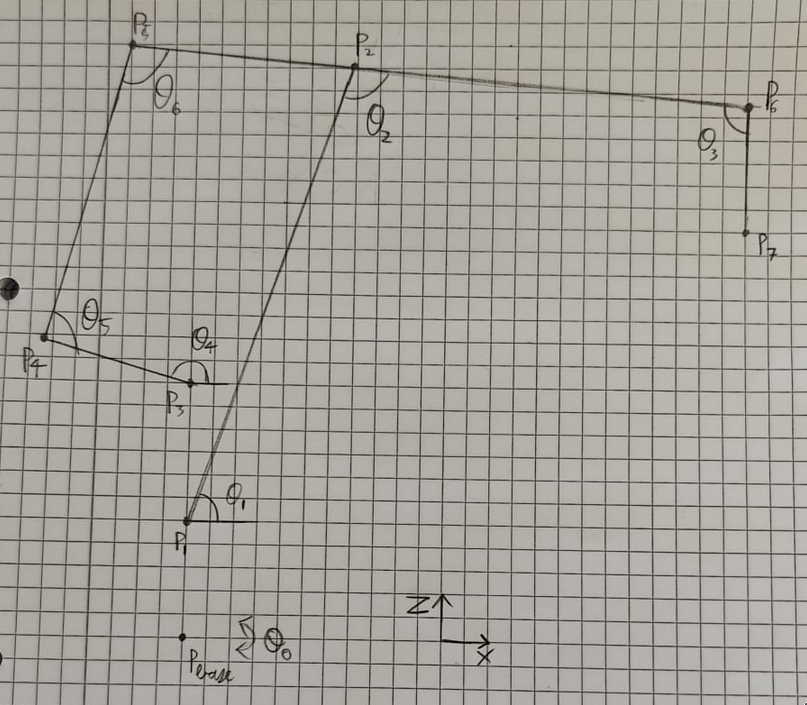
In the all the following code blocks, there will be different types of variables used.
Variables that start with a P represent points,
variables that start with a T represent transform that can be performed on points,
and variables that start with an L are scalar length values.
Note: all angles are measured in radians, and all lengths are measured in meters.
Forward kinematics
The input arguments of the function are the actuated angles of the arm, since these are the only ones measurable by the encoders.
The function returns the projected end position of the end effector.
function [x, y, z] = forward_kinematics(theta0, theta1, theta3, theta4)
    %defining dimentions
    LbaseToP1 = 0.065;
    LbaseToP3 = 0.149;

    LP1toP2 = 0.350;
    LP5toP6 = 0.620;
    LP5toP2 = 0.120;
    LP6toP7 = 0.300;

    LP3toP4 = 0.120;
    LP4toP5 = 0.280;
The first thing that happens in the forward kinematics is the definition of the dimensions of the different joints, these values are gotten from measuring the physical arm.
The point representing the base rotation (Pbase) is rotated theta0 radians.
%rotation z
TP0toPbase = [cos(theta0) -sin(theta0) 0 0;
              sin(theta0)  cos(theta0) 0 0;
              0            0           1 0;
              0            0           0 1];
From therethere, all the known transforms to the different points are defined, the transforms are defined with the main idea being, rotation happens along the Z-axis, and translation happens along the X-axis. This is done by first translating shoulder actuated points (P1 and P3) and then rotating them along the x axis.
%translation z then rotation x
TPbasetoP1 = [1 0 0  0;
              0 0 -1 0;
              0 1 0  LbaseToP1;
              0 0 0  1];

%rotation z
TPbasetoP1 = TPbasetoP1 * [cos(theta1) -sin(theta1) 0 0;
                           sin(theta1)  cos(theta1) 0 0;
                           0            0           1 0;
                           0            0           0 1];
%translation z then rotation x
TPbasetoP3 = [1 0 0 0;
0 0 -1 0;
0 1 0 LbaseToP3;
0 0 0 1];
%rotation z
TPbasetoP3 = TPbasetoP3 * [cos(theta4) -sin(theta4) 0 0;
sin(theta4) cos(theta4) 0 0;
0 0 1 0;
0 0 0 1];The reason that they are rotated twice is because it is easier to keep track of the relative positions and angles involved.
After that, the other currently inferrable transforms are defined.
%translation x
TP1toP2 = [1 0 0 LP1toP2;
           0 1 0 0;
           0 0 1 0;
           0 0 0 1];

%translation x then rotation z
TP5toP6 = [cos(theta3) -sin(theta3) 0 LP5toP6;
           sin(theta3)  cos(theta3) 0 0;
           0            0           1 0;
           0            0           0 1];

%translation x
TP6toP7 = [1 0 0 LP6toP7;
           0 1 0 0;
           0 0 1 0;
           0 0 0 1];

%translation x
TP3toP4 = [1 0 0 LP3toP4;
           0 1 0 0;
           0 0 1 0;
           0 0 0 1];
Some of these transforms don't have rotations, this is because we either don't know the angle rotation yet, or it is an end point, that does not have to be moved and by extension rotated further.
Due to the construction of the arm, some calculations have to be done to find the rest of the unknown angles.
This is done by first defining an initial position, and then some theoretical "planar" positions of the points P2 and P4.
%initial position
P0 = [1 0 0 0;
      0 1 0 0;
      0 0 1 0;
      0 0 0 1];

%getting position for paralellagram angles
P2planar = P0 * TPbasetoP1 * TP1toP2;
P4planar = P0 * TPbasetoP3 * TP3toP4;
The reason they are planer is because they were produces without any base rotation, so they all lay on the y=0 plane.
After that, a small inverse kinematics equation is performed to find the angles theta5 and theta6, which is done using a standard formula.
L_1 = LP4toP5; L_2 = LP5toP2;
XE = P4planar(1, 4) - P2planar(1, 4);
YE = P4planar(3, 4) - P2planar(3, 4);
theta5 = 2*atan((2*L_1*YE + sqrt(- L_1^4 + 2*L_1^2*L_2^2 + 2*L_1^2*XE^2 + 2*L_1^2*YE^2 - L_2^4 + 2*L_2^2*XE^2 + 2*L_2^2*YE^2 - XE^4 - 2*XE^2*YE^2 - YE^4))/(L_1^2 + 2*L_1*XE - L_2^2 + XE^2 + YE^2));
theta6 = -2*atan(sqrt((- L_1^2 + 2*L_1*L_2 - L_2^2 + XE^2 + YE^2)*(L_1^2 + 2*L_1*L_2 + L_2^2 - XE^2 - YE^2))/(- L_1^2 + 2*L_1*L_2 - L_2^2 + XE^2 + YE^2));
%adding pi-theta4 to make the actual rotation angle
theta5 = theta5+(pi-theta4);
Now that we know all the angles, the rest of the transforms can be defined.
%translation x then rotation z
TP3toP4 = [cos(theta5) -sin(theta5) 0 LP3toP4;
           sin(theta5)  cos(theta5) 0 0;
           0            0           1 0;
           0            0           0 1];

%translation x then rotation z
TP4toP5 = [cos(theta6) -sin(theta6) 0 LP4toP5;
           sin(theta6)  cos(theta6) 0 0;
           0            0           1 0;
           0            0           0 1];
And now we have all the transforms, we can calculate all the points.
%calculating all needed points
Pbase = TP0toPbase;
P3 = Pbase * TPbasetoP3;
P4 = P3 * TP3toP4;
P5 = P4 * TP4toP5;
P6 = P5 * TP5toP6;
P7 = P6 * TP6toP7;
Finally, the final position of the end effector can be read from the final point.
%extracting position
x = P7(1,4);
y = P7(2,4);
z = P7(3,4);
end