
Gripper
The first version of the gripper was designed and prototyped for a minor assignment with PD&D (Product Design & Development). The full report includes the detailed Literature review, Conceptualisation, Concept Evaluation, Design and Prototyping Phase, as well as motor choices, transmission ratios, and material selections. The report can be found in the Roboteam Twente 2025-2026 folder at the following location:
The report can also be found by clicking on the following link:
https://drive.google.com/file/d/1Wu9a8M1p-OKg_CWaNAc5rW-M6DI_p-xK/view?usp=sharing
1. Summary & Content of report
2. Requirements
Based on the task description and the literature review, the following requirements were set with the following weighting of importance:
(a) The gripper must weigh less than 2 kg (20%).
(b) The gripper must provide precise and accurate manipulation of buttons measuring 15×15 mm (20%).
(c) The gripper must be able to grasp rocks larger than 15 cm (10%).
(d) The gripper must be able to carry rocks larger than 15 cm (10%).
(e) The gripper should have a low-cost actuation system (10%).
(f) The length of the gripper must be less than 30 cm (10%).
(g) The gripper must provide one accurate rotation (1-DOF) (10%).
(h) The gripper diameter must be equal to or less than 10 cm (5%).
(i)The gripper must provide force closure (5%).
(j) The gripper must provide form closure (5%).
(k) The gripper should be easy to maintain (5%).
3. System Description & CAD models
Figure 1a and Figure 1b illustrate the full gripper and its subassemblies. The design is divided into three main subassemblies: the jaws’ assembly, the planetary gearbox, and the connection to the robotic arm. The design phase aimed to ensure that two gripper configurations would be possible: a two-jaw configuration and a four-jaw configuration. Both configurations use soft, compliant, reinforced jaws, actuated by a worm gearbox. The jaws’ rest position is closed, as compression springs are located under each jaw. The springs are used to minimise the motor requirements in torque and enhance the force closure.
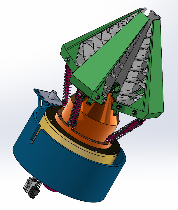
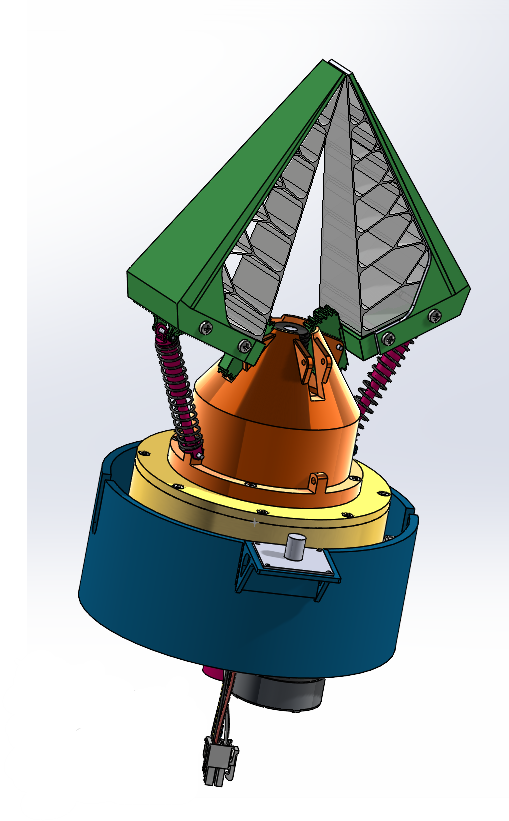
Figure 1a: Full assembly of four-jaw configuration blah Figure 1b: Full assembly of two-jaw configuration
A planetary gearbox ensures the rotation of the gripper around its centre axis. The sun gear allows for the cables of the jaws motor and force sensors to connect to the rest of the system. The wrist pitch is actuated by a DC motor combined with a planetary gear head. The gear head is connected to a 1:1 pulley-belt drive. Overall, the gripper utilises three DC motors, three encoders, three motor drivers, and two force sensors. Additionally, the gripper carries a camera used for Business Logic during maintenance and sampling tasks. The video feed is sent to the computer vision system.
All components and their CAD models are listed in the Excel sheet located in the drive:
Or by clicking on the following link:
https://docs.google.com/spreadsheets/d/1X3AsVIhJ1_YzZIhLjmNuEIaihkdtOWf1gauOEwgxZvM/edit?usp=sharing
4. Current Challenges (ERC 2026)
During the prototyping and integration phases, several issues were identified in the current gripper design:
- Housing fragility:
- Planetary gearbox connection:
- Wrist connection:
- Inefficient configuration change:
- Sensor absence:
- Water-tight camera container:
5. Ideas & Future Improvements
- Automatic configuration change:
- Redesign of the housing:
- Redesign of the connection point of the planetary gearbox:
- Redesign of wirst connection to the belt drive:
- Improvement of the watertightness of the camera holder:
- Modular gripper: