
CAN BUS TestBench
CAN BUS debugging testbench
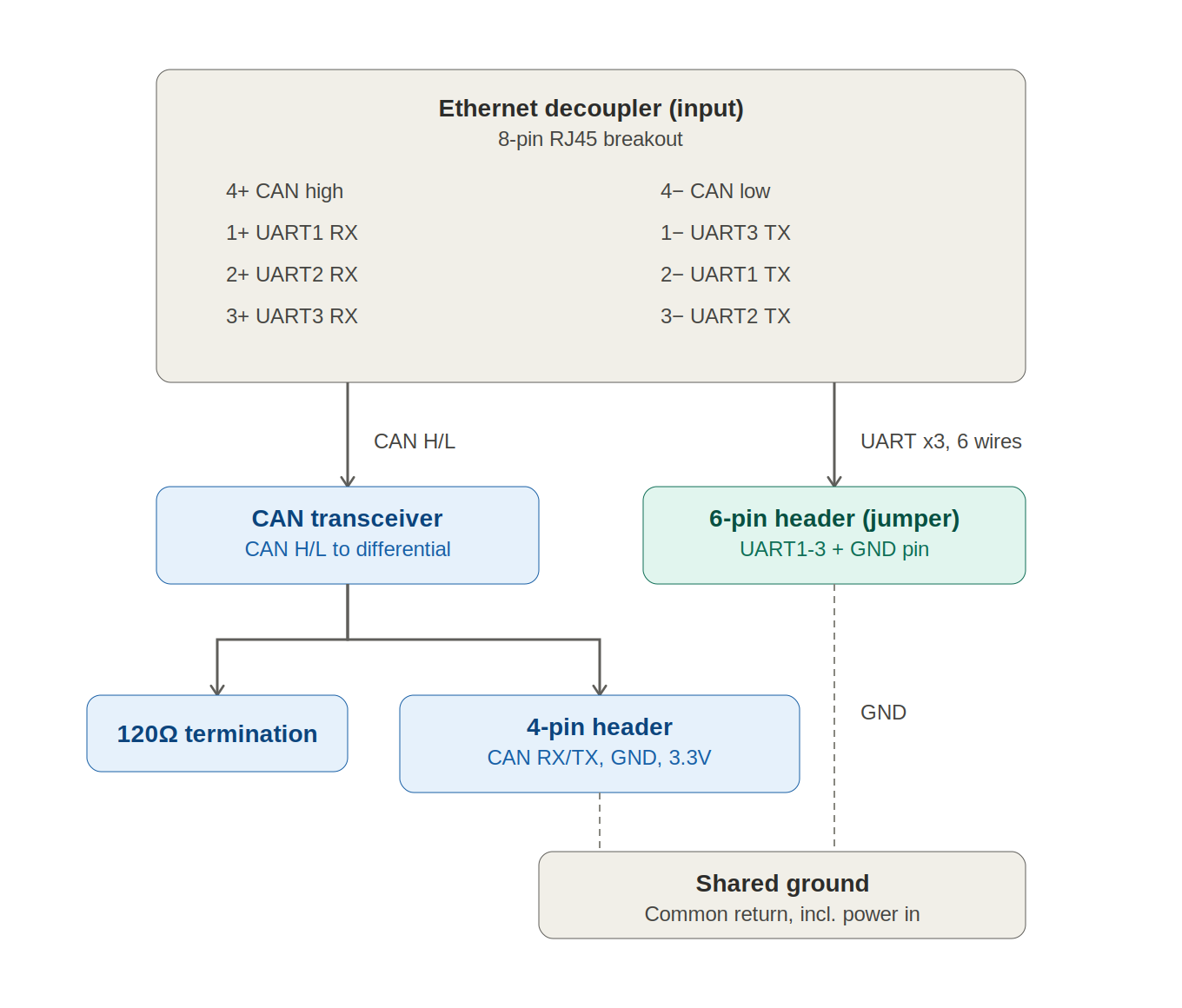
A breakout board for debugging connecting and developing CAN BUS peripherals (used mainly for CubeMars motors) over CAN and UART, built around an ethernet decoupler as the physical input connector. It exposes CAN H/L on a 4-pin header and UART1-3 on a 6-pin jumper header, with a shared ground. It assumes you are using the ethernet wire layout used in the driving system
Wiring
The board takes a single ethernet cable as input. The decoupler splits the 8 conductors into two logical groups: a differential CAN pair and three UART pairs.
Input: ethernet decoupler (8-pin)
Pin | Signal |
|---|---|
4+ | CAN high |
4- | CAN low |
1+ | UART1 RX |
1- | UART3 TX |
2+ | UART2 RX |
2- | UART1 TX |
3+ | UART3 RX |
3- | UART2 TX |
The UART connections can be used to debug and interact with devices alongside CAN, as diagnosing wiring/CAN implementation issues can be narrowed down by knowing UART communication works
CAN branch
CAN high and CAN low run from the decoupler into a CAN transceiver, which converts the differential pair into logic-level CAN RX/TX. From there:
- The bus is terminated with a 120Ω resistor across CAN H/L, as required for a properly terminated CAN segment (prevents signal reflections at the ends of the bus).
- The transceiver's logic-level signals break out to a 4-pin header: CAN RX, CAN TX, GND, 3.3V. This is the connector you'd plug a CAN-capable microcontroller or CAN-USB adapter into.
UART branch
The three UART pairs (1+/1-, 2+/2-, 3+/3-) route directly from the decoupler to a 6-pin header, laid out for standard jumper cables. Each of UART1, UART2, and UART3 gets its own RX/TX pair on this header.
UART is currently not working, it is probably a very simple wiring issue, but we had no time to look into it
Shared ground
A single ground pin sits next to the 6-pin UART header and is shared across the whole board — the 4-pin CAN header's GND, the 6-pin UART header's GND, and any power input all return to this same node. There's one ground reference for the entire testbench, not separate isolated grounds per connector.
How to use it
- Connect the input. Plug an ethernet cable that uses the standard CAN connection that are used in the rover
- Pick your interface.
- For CAN: connect a CAN transceiver-compatible device (e.g. a CAN-USB dongle, or a microcontroller with a CAN controller) to the 4-pin header. Power it from the 3.3V/GND pins if it needs board power, or use its own supply and just tie grounds together.
- For UART: connect jumper wires from the 6-pin header to your microcontroller's UART peripheral(s). Match RX↔TX and TX↔RX per channel, and connect the shared GND pin.
- Check ground first. Since ground is shared across everything on this board, always connect GND before or alongside signal lines when hooking up test equipment, to avoid floating references skewing your readings.
- Probe or sniff. With connections made, you can scope the CAN H/L lines directly at the transceiver's input side, or log traffic on RX/TX at the 4-pin/6-pin headers depending on which layer you're debugging.
3D printing an enclosure
An enclosure/mount for this testbench is available as an STL file: cubemars-testbench-enclosure.stl