
Manual control
Overview
In general, the job of the control system is to turn high level instructions from the software system, and turn them into instructions for the hardware. This is done by having a distance to a goal, a turning radius, and a deltaTime as an input, and turning those into control signals for the motors:
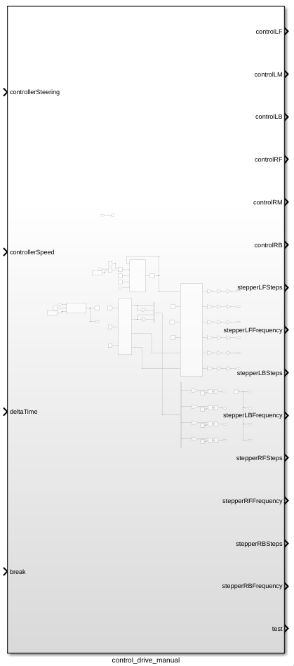
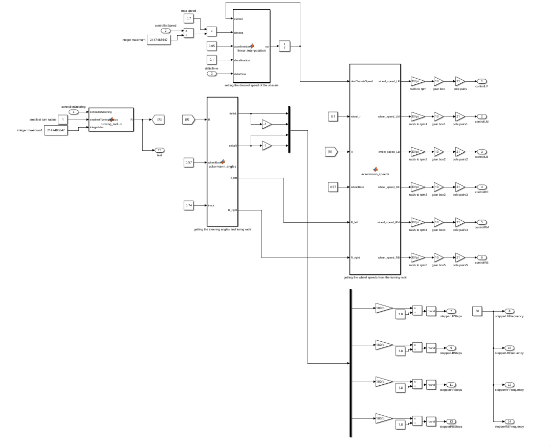
This is done in several steps.
Determining current desired speed and turning radius
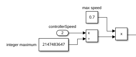
To determine what speed the rover should move at this moment, it takes the input from the controller, and scales it to a speed value between 0 and 0.7.
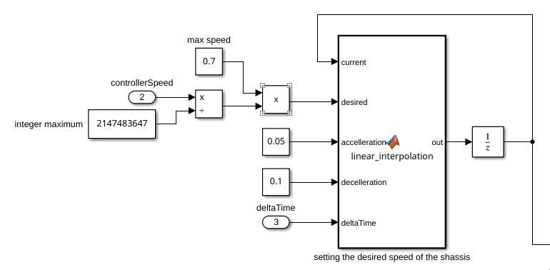
This output speed sent passed though a linear interpolation function, to make sure the acceleration and deceleration stays consistent.
The turning radius is gotten in a very similar way as the desired speed, scaling the controller input to a correct turning radius.
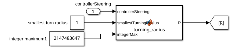
The function block looks like this:
function R = turning_radius(controllerSteering, smallestTurningRadius, integerMax)
    %exiting early if controllerSteering is close to 0
    if abs(controllerSteering) < 20
        R = 0;
        return;
    end
    %computing turning radius from controller input
    R = smallestTurningRadius/(controllerSteering/integerMax);
end
Ackermann steering
Getting the necessary angles that the steering motors need to make is done by calculating the Ackermann steering angles that equate from the given turning radius, wheelbase, and track of the rover.
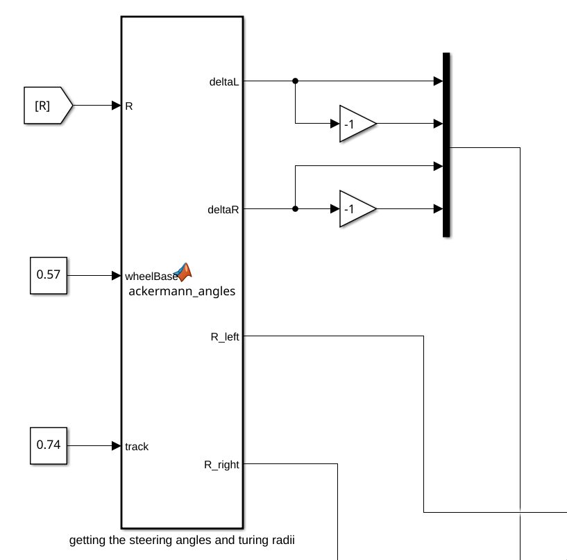
deltaL and deltaR are equal to the angles that the left and right steering motors need to make, which are sent to the steering control.
This function also outputs the turning radius of the right and left wheels of the rover.
The function works like this:
function [deltaL,deltaR,R_left,R_right] = ackermann_angles(R,wheelBase,track)
    % Function to compute ackerman steering angles
    if R < 0
        R_left = (R+track/2);
        R_right = (R-track/2);
        deltaL = atan(wheelBase/(R_left));
        deltaR = atan(wheelBase/(R_right));
    elseif R > 0
        R_left = (R-track/2);
        R_right = (R+track/2);
        deltaL = -atan(wheelBase/(R_left));
        deltaR = -atan(wheelBase/(R_right));
    else
        deltaL = 0;
        deltaR = 0;
        R_left = R;
        R_right = R;
    end
end
Ackermann speeds
Using the data coming from the previous function, as well as a wheel radius and motor gear ratio, the speeds needed by the motors are calculated.
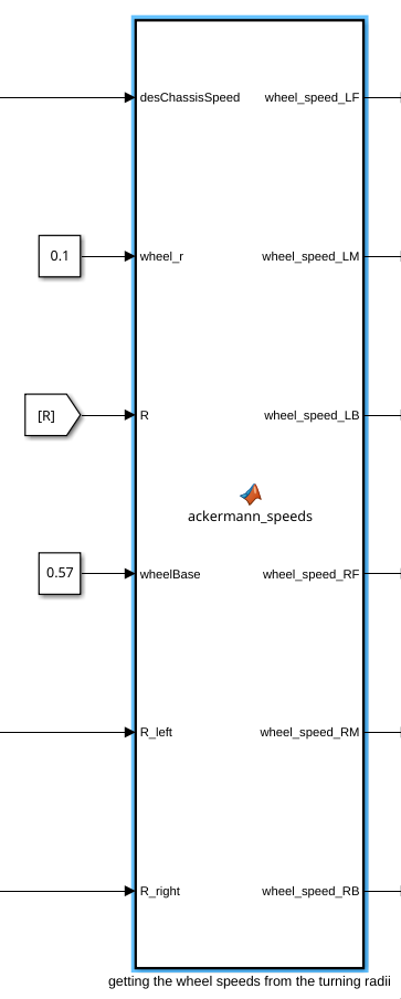
Internally the function works like this:
function [wheel_speed_LF,wheel_speed_LM,wheel_speed_LB,wheel_speed_RF,wheel_speed_RM,wheel_speed_RB] = ...
          ackermann_speeds(desChassisSpeed,wheel_r,R,wheelBase,R_left,R_right)
    %all speeds the same if the rover is not turning
    if R == 0
        wheel_speed_LF = desChassisSpeed / wheel_r;
        wheel_speed_LM = desChassisSpeed / wheel_r;
        wheel_speed_LB = desChassisSpeed / wheel_r;
        wheel_speed_RF = desChassisSpeed / wheel_r;
        wheel_speed_RM = desChassisSpeed / wheel_r;
        wheel_speed_RB = desChassisSpeed / wheel_r;
    else
        wheel_speed_LF = (desChassisSpeed/wheel_r)*sqrt(R_left^2 + (wheelBase/2)^2)/R;
        wheel_speed_LM = desChassisSpeed * R_left/(R*wheel_r);
        wheel_speed_LB = (desChassisSpeed/wheel_r)*sqrt(R_left^2 + (wheelBase/2)^2)/R;
        wheel_speed_RF = (desChassisSpeed/wheel_r)*sqrt(R_right^2 + (wheelBase/2)^2)/R;
        wheel_speed_RM = desChassisSpeed * R_right/(R*wheel_r);
        wheel_speed_RB = (desChassisSpeed/wheel_r)*sqrt(R_right^2 + (wheelBase/2)^2)/R;
    end
end
Control signals
DC motors
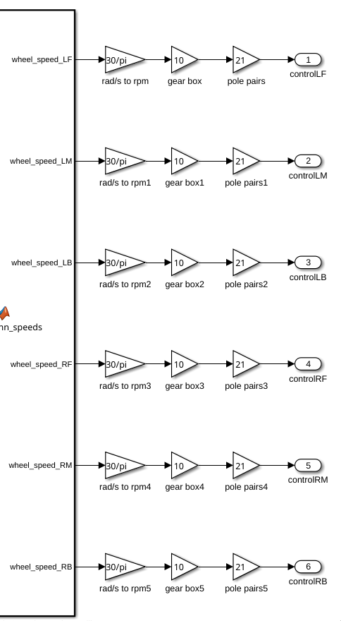
After getting all the angles and speeds needed for the rover to make a certain movement, the signals get sent to the motor drivers/controllers in terms of ERPM.
Stepper motors
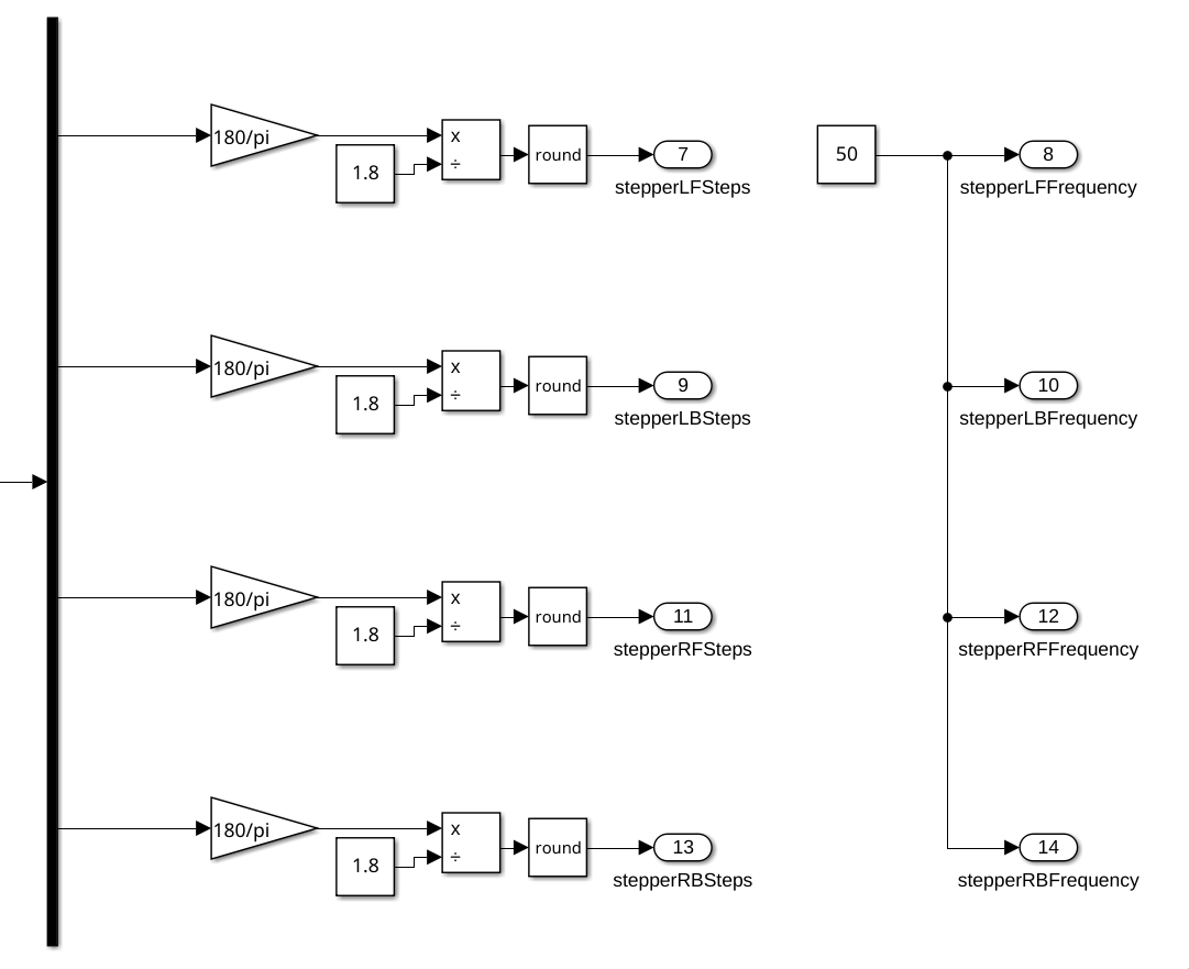
Due to the limitations of Simulink, making the stepper motors move is done using PWM signals coming from the STM32 microcontrollers. The control system only gives the desired position of the stepper motors in terms of steps, and a frequency at which the PWM signal pulses, which in this case is just a constant value.
The sending of the PWM signals is handled by the embedded team.