Mechanics
Base
Parallel Linkage
1. Requirements
The structure of the robotic arm is the connection point between the rover and the end-manipulator. Hence, it is crucial to aim for a large reach and a lightweight dynamic structure that can support the loaded gripper and allow for precise motion. During the academic year 2025-2026, the aim was to develop Before starting the design phase, a list of requirements was set:
(a) The robotic arm shall reach a distance of around 1 meter when fully extended in any direction.
(b) The robotic arm shall aim for an overall lightweight design (less than 10kg)
(c) The robotic arm shall be easy to mount on the rover (5-10 minutes mounting time)
(d) The robotic arm shall be easy to disassemble (<30 minutes)
(e) The robotic arm shall be easy to assemble (<30 minutes)
(f) The mounting of all actuators shall consider cable management.
(g) Off-the-shelf components are prioritised during design and assembly
(h) The manufacturing of all parts shall be possible within the university infrastructures
2. Concept & Motivation
A parallel linkage was chosen as the structure of the robotic arm for weight reduction purposes. During early design phases, it was observed that the shoulder motor (see Figure 1) would require significantly higher torque requirements to handle the rest of the arm. These high torque requirements are induced by the considerable length of the robotic arm (aiming for a reach of around 1 m) but also because of the weight created by the elbow motor that results in a significant increase in inertia.
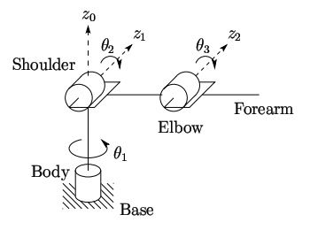
Figure 1: Kinematic diagram of traditional robotic arms and joint names [1].
To address these challenges, we opted to utilise a parallel linkage for the robotic arm's structure (see Figure 2). This structure groups the 2DOFs (θ2 and θ3) at the base of the linkage, minimising the inertia of the entire robotic arm. The disadvantages of this structure include a reduced reach, as it is physically challenging to extend the arm fully, but also a less instinctive arm design that might result in control challenges. After evaluating all factors influencing the design (motor selection, design components and manufacturing), it was decided that the parallel linkage remains an interesting trade-off for the whole system and hence was selected as the final concept.
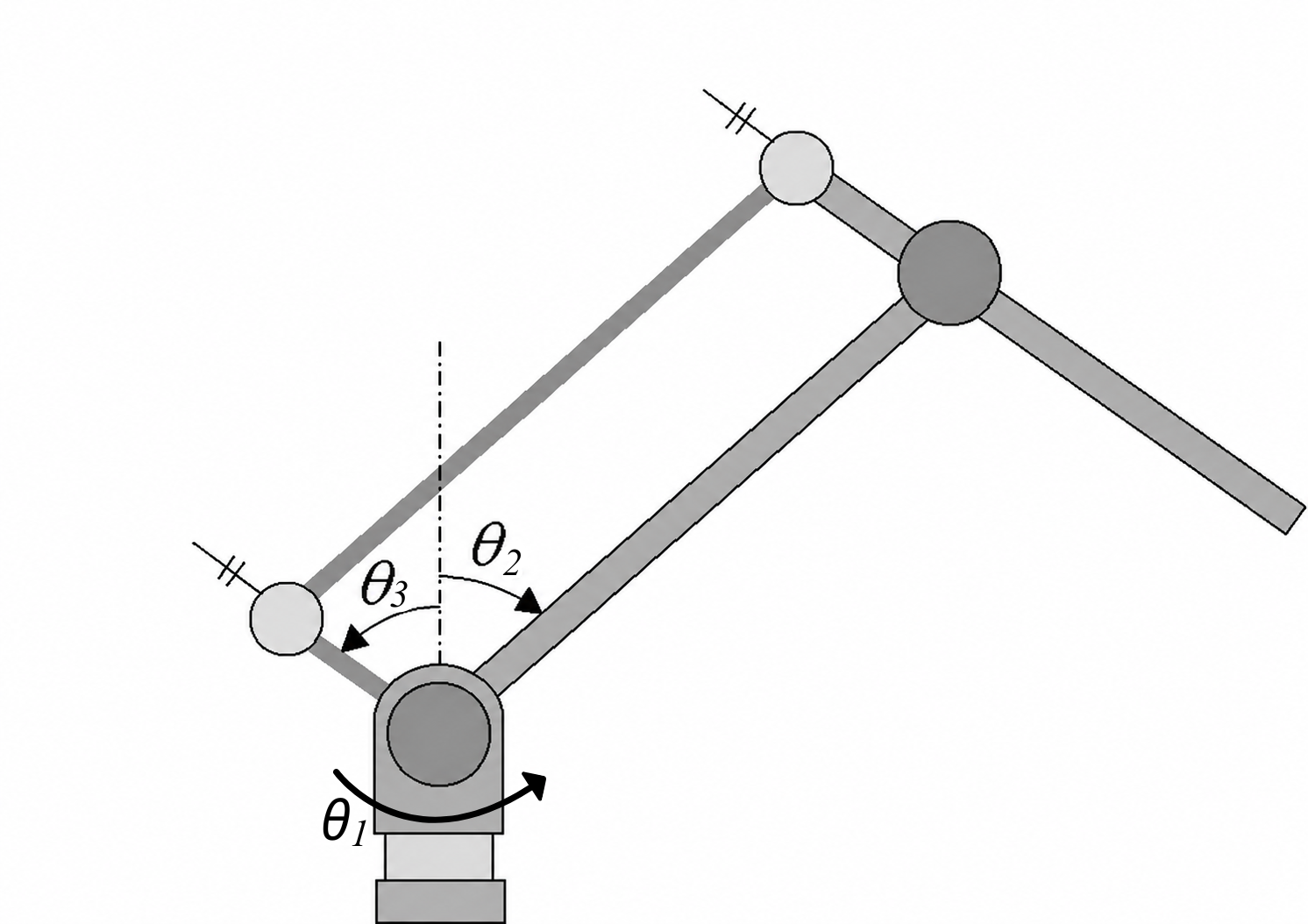 Figure 2: Kinematic diagram of parallel linkage [2].
3. Design & Materials
Figure 3 shows the final execution of the parallel linkage concept presented in the last section. A 3D-printed circular base is used as a connection point with the Base assembly. Four 3D-printed vertical plates are used to mount the two motors and gearboxes that actuate the two shoulder actuations (θ2 and θ3). The wrist actuation of the end-manipulator (moving the gripper up and down, see the Gripper page) uses a DC motor located in the middle of the forearm to reduce inertia and avoid mounting the gripper directly on the motor. A 1:1 belt drive transfers the torque from the DC motor to the gripper.
All plates used in the parallel linkage were laser-cut from 3 mm-thick aluminium sheets ordered from MCB Direct. All shafts that were not included in a motor or a gearbox were turned at CUBE, from raw material ordered from RS. Five deep-groove ball bearings were used to support all moving shafts within the parallel linkage (16101). All pulleys are 3D-printed due to manufacturing challenges to fit the gearbox and motor shafts. The belts were ordered from RS. The aluminium sheets are mounted and held together by standoffs from RS. This structure is called a 'sandwich'. The top sandwich (or forearm) uses a combination of two M4 standoffs (50 mm and 60 mm) to reach a size of 110mm. The bottom sandwich uses M4x40 mm standoffs.


spacespacespacespacespa(a)spacespacespacespacespacespacespacespacespacespace (b)
Figure 3: Full assembly of the parallel linkage, where (a) shows the connections with the shoulder motor and gearboxes, the integration of the wrist motor, and the connection to the gripper, and (b) shows the side view of the assembly, where the final design of the parallel linkage is clearly visible.
The stepper motors (ST5918M3008-B) and gearboxes (GPLE60-3S-80) actuating the shoulder DOFs are from Nanotec. Additionally, the stepper motors were ordered with an additional encoder (NTO3-05-C06 (6.35 mm)) and brake (BRAKE-BCD56-1,5-8). The wrist motor (AK45-10) was bought from CubeMars.
References:
[1] Gupta, Ayush & Chourika, Sameer & Agrawal, Sankalp & Deshmukh, Ankur & Bhargava, Prasham. (2018). A Geometric Approach to Inverse Kinematics of a 3 DOF Robotic Arm.
[2] Ahn, Kuk‐Hyun et al. “Reduction in gravitational torques of an industrial robot equipped with 2 DOF passive counterbalance mechanisms.” 2016 IEEE/RSJ International Conference on Intelligent Robots and Systems (IROS) (2016): 4344-4349.
Gripper
The first version of the gripper was designed and prototyped for a minor assignment with PD&D (Product Design & Development). The full report includes the detailed Literature review, Conceptualisation, Concept Evaluation, Design and Prototyping Phase, as well as motor choices, transmission ratios, and material selections. The report can be found in the Roboteam Twente 2025-2026 folder at the following location:
The report can also be found by clicking on the following link:
1. Summary & Content of report
A) Literature Review
Various existing manipulator technologies, including parallel jaw grippers, underactuated dexterous hands, and soft grippers such as those utilizing the Fin-Ray Effect (FRE) were researched and analysed. The review also evaluates actuation systems, comparing traditional gearboxes with high-efficiency cycloidal and harmonic drives, and contrasting electric motors with pneumatic alternatives.
B) Conceptualization
Six initial concepts were proposed and evaluated using a weighted rating system. The evaluation identified the strengths of FRE jaws (Concept 6) and the planetary gearbox rotation mechanism (Concept 4). These were combined into a final hybrid design (Concept 7), which achieved the highest overall score for its balance of compliance, torque, and weight.
C) Design and Justification
This section details the mechanical architecture of the final gripper, featuring branched FRE jaws for maximum compliance and a worm gearbox that provides high torque output while minimizing motor strain. It also describes a planetary gearbox for 1-DOF rotation and a specialized slip ring assembly to manage cabling without tangling during rotation.
D) Prototyping and Materials
The prototype was manufactured using FDM 3D printing to allow for rapid iterations. Material selection was critical: TPU was used for flexible jaws to ensure a high-friction grip, PETG was chosen for structural plates due to its tensile strength, and carbon-fiber-reinforced PETG (rCF08) was utilized for gears to improve wear resistance.
E) Results and Discussion
Functional testing confirmed that the prototype could successfully grasp a 2.1 kg rock and perform delicate tasks such as typing on a keyboard and plugging in a USB-B connector. While the gripper met weight and length goals, it exceeded the 10 cm diameter limit and required tedious manual effort to switch between two-jaw and four-jaw configurations.
F) Conclusion
The report concludes that the FRE-based multipurpose gripper is a promising and efficient solution for the Cydonia rover. Future improvements will focus on dimensional optimization to reduce the overall diameter and the integration of force sensors for more precise feedback and control
2. Requirements
Based on the task description and the literature review, the following requirements were set with the following weighting of importance:
(a) The gripper must weigh less than 2 kg (20%).
(b) The gripper must provide precise and accurate manipulation of buttons measuring 15×15 mm (20%).
(c) The gripper must be able to grasp rocks larger than 15 cm (10%).
(d) The gripper must be able to carry rocks larger than 15 cm (10%).
(e) The gripper should have a low-cost actuation system (10%).
(f) The length of the gripper must be less than 30 cm (10%).
(g) The gripper must provide one accurate rotation (1-DOF) (10%).
(h) The gripper diameter must be equal to or less than 10 cm (5%).
(i)The gripper must provide force closure (5%).
(j) The gripper must provide form closure (5%).
(k) The gripper should be easy to maintain (5%).
3. System Description & CAD models
Figure 1a and Figure 1b illustrate the full gripper and its subassemblies. The design is divided into three main subassemblies: the jaws’ assembly, the planetary gearbox, and the connection to the robotic arm. The design phase aimed to ensure that two gripper configurations would be possible: a two-jaw configuration and a four-jaw configuration. Both configurations use soft, compliant, reinforced jaws, actuated by a worm gearbox. The jaws’ rest position is closed, as compression springs are located under each jaw. The springs are used to minimise the motor requirements in torque and enhance the force closure.


Figure 1a: Full assembly of four-jaw configuration blah Figure 1b: Full assembly of two-jaw configuration
A planetary gearbox ensures the rotation of the gripper around its centre axis. The sun gear allows for the cables of the jaws motor and force sensors to connect to the rest of the system. The wrist pitch is actuated by a DC motor combined with a planetary gear head. The gear head is connected to a 1:1 pulley-belt drive. Overall, the gripper utilises three DC motors, three encoders, three motor drivers, and two force sensors. Additionally, the gripper carries a camera used for Business Logic during maintenance and sampling tasks. The video feed is sent to the computer vision system.
All components and their CAD models are listed in the Excel sheet located in the drive:
Or by clicking on the following link:
https://docs.google.com/spreadsheets/d/1X3AsVIhJ1_YzZIhLjmNuEIaihkdtOWf1gauOEwgxZvM/edit?usp=sharing
4. Current Challenges (ERC 2026)
During the prototyping and integration phases, several issues were identified in the current gripper design:
- Housing fragility: The current housing of the worm gear has been the main breaking point of all prototypes. Specifically, the housing breaks at the connection point between the worm wheels and the housing, especially when the gripper faces resistance and must provide higher torque.
- Planetary gearbox connection: The planetary gearbox is very difficult to assemble and, hence, to troubleshoot in case of damage. This issue is also time-consuming and unpredictable, as components can break during assembly and require a newl printed components.
- Wrist connection: The connection of the gripper to the rest of the arm is done by a bracket that is attached to a belt drive system (wrist connection). The wrist connection is currently wiggly, which leads to inaccurate control. Additionally, the connection to the gripper is relatively complicated.
- Inefficient configuration change: To change from one configuration to another, the users must retrieve M2 bolts and nuts. By taking out the bolts and nuts, the spring assemblies are completely disconnected and very easy to lose. Additionally, the M2 bolts and nuts are challenging to reassemble.
- Sensor absence: Due to time constraints, the force sensors on the jaws' reinforcements were never integrated with the gripper.
- Water-tight camera container: The container was printed as a quick prototype, where hot glue was used to create watertightness. Because the glue was unevenly applied, the camera holder could leak and damage the camera.
5. Ideas & Future Improvements
- Automatic configuration change: To solve the inefficient configuration change, the housing could be modified to create an automatic configuration change mechanism. The challenge of this project is to implement an actuator that can roughly fit within the current design. Another challenge is the design of the housing to mechanically follow the actuation without breaking any permanent connection.
- Redesign of the housing: The housing must also be redesigned to guarantee that it will be able to support the high torque transmitted by the jaws on the manipulated object without breaking. During this redesign, the goal should also be to preserve the sturdy connection with the DC motor and planetary gearbox.
- Redesign of the connection point of the planetary gearbox: Connecting the planetary gearbox with its actuator and the bottom plate of the gripper remains quite inefficient for several reasons. First, Loctite is applied on the three M4 'shafts' (currently threaded rods within the prototype) to lock the nuts in place and ensure they do not fall out of the system due to the rotation of the gearbox. Then, the Loctite is a relatively permanent connection. Hence, in case a gear must be replaced, one must pour and rub acetone on the nuts and pull in very chaotic ways to disassemble the bottom plate and access the rest of the system. Improving the connection mechanism of the planetary gearbox with the rest of the system will make the gripper easier to analyse, fix and improve.
- Redesign of wirst connection to the belt drive: To fix the wrist connection, one must redesign the brackets, especially the connection to the gripper. Another solution would be to replace the brackets with one piece connected at the centre of the gripper and the centre of the actuated shaft in the belt drive system. Further research on potential solutions could be done by performing a literature review on robotic wrist design articles.
- Improvement of the watertightness of the camera holder: The camera cap should be connected with four screws instead of two. Additionally, a TPU insert could be added as a guarantee that no leakage will occur.
- Modular gripper: Similar to the automatic configuration change, making this design modular to be able to exchange the type of jaws or add a scoop for regolith manipulation, or even exchange the jaws with a tube holder to safely collect liquid with the liquid collector (see chassis book).