**Make sure you understand the embedded structure:** [Embedded Infastructure](https://bookstack.roboteamtwente.nl/books/embedded-infastructure "Embedded Infastructure")
--- ## 1) MainMain.c can be found in `src/arm_board`
This is the code that will be ran when building and uploading using platformio. Main should contain some multithreading for running separate tasks, otherwise it should use the libraries (common and arm board specific) that are created. --- ## 2) LibrariesThe libraries for the arm board can be found in `components/arm_board`
The arm board uses 3 libraries: - firmware - movement - simulink **Firmware** contains the generated CubeMX code. You do not need to touch this after generating.**NOTE:** do make sure that after generating your code in CubeMX, you run the post generation script. You **can** set a post generation script in CubeMX itself. However, if you use **Windows** you may need to run the bash script manually. This script can be found in `scripts/post_code_generation.bash`.
**Simulink** contains code generated by control subteam. You also do not need to touch this, since it is not code that is ran on embedded side. It is a helpful **reference** for the output data that control will be giving your system. Specifically, in `control.h`, struct `ExtY` gives the external outputs. These will be transferred across the robot using protobufs. So for us, this struct contains the inputs for the motors on the robotic arm. **Movement** is currently the only "real" library that is written by hand. It contains the source code for controlling stepper motors. --- ## 3) Protobuffers**Information on the arm board protobuffers can be found here:** [Arm Board Protobuffers](https://bookstack.roboteamtwente.nl/books/communication-system/page/arm-board-protobuffers "Arm Board Protobuffers")
# Example PWM generation ***This page:** *what does the configuration look like for my board, specifically regarding PWM.**Make sure you have set up Ethernet according to the following page **FIRST**: [Introduction and initial setup of embedded ethernet](https://bookstack.roboteamtwente.nl/books/communication-system/page/setup-of-embedded-ethernet "Introduction and initial setup of embedded ethernet")
--- ## **PWM** > **Pulse Width Modulation** (PWM) is a technique for generating a continuous HIGH/LOW alternating digital signal and programmatically controlling its pulse width and frequency. Certain loads like (LEDs, Motors, etc) will respond to the **average voltage** of the signal which gets higher as the PWM signal’s pulse width is increased. This technique is widely used in embedded systems to control LEDs brightness, motor speed, and other applications. > > [DeepblueMbedded.com](https://deepbluembedded.com/stm32-pwm-example-timer-pwm-mode-tutorial/) On the embedded subteam, we use PWM to control the motors for the Robotic arm and [Drive system](https://bookstack.roboteamtwente.nl/books/drive-system "Drive system"). In the world of PWM, two metrics are most important: **duty cycle** and **frequency**. The duty cycle is determined by the percentage of high/low signal, for example a 75% duty cycle means that the signal is HIGH 75% of the time. How long this total time is, is determined by the frequency. The frequency is to determine motor speed. [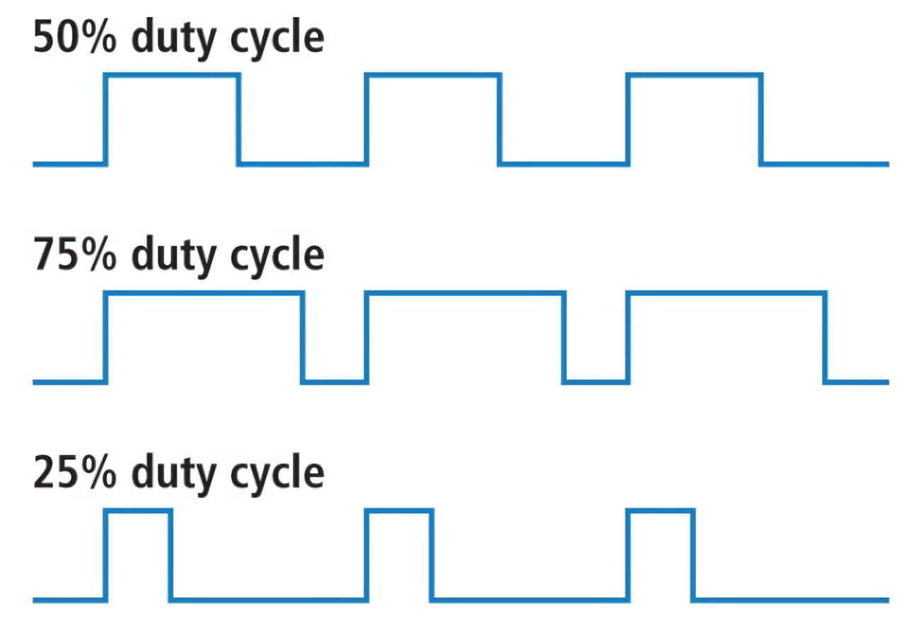](https://bookstack.roboteamtwente.nl/uploads/images/gallery/2026-04/NaAafbeelding.png) --- ## **CubeMX**Make sure you have set up Ethernet according to the following page **FIRST**: [Introduction and initial setup of embedded ethernet](https://bookstack.roboteamtwente.nl/books/communication-system/page/setup-of-embedded-ethernet "Introduction and initial setup of embedded ethernet")
### 1) Setting Pins The only pin that is set at the moment (except for defaults) is **PA0**. It is set to TIM2\_CH1, this means it uses Timer 2 Channel 1 for something, in this case it is PWM generation. [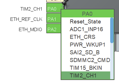](https://bookstack.roboteamtwente.nl/uploads/images/gallery/2026-04/ze1afbeelding.png) If we want to set more pins to generate PWM signals, we can use a workflow similar to what will be described below. Of course, you will need to choose a **separate timer** for each pin. Also make sure that the pin is **suitable** for PWM! ##### **TIM2 > Mode** After you have set the pin, you need to enable the timer and channel to do something. We set `Clock Source: Internal Clock` to enable the timer and `Channel1: PWM Generation CH1 `to use PWM on pin PA0. [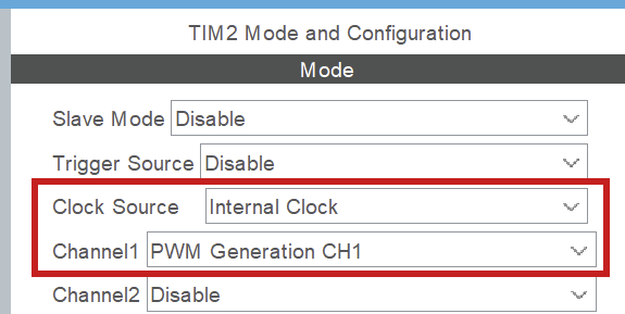](https://bookstack.roboteamtwente.nl/uploads/images/gallery/2026-04/a8Xafbeelding.png) ##### **TIM2 > Configuration > NVIC settings** Enable global interrupt. [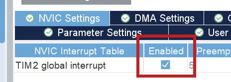](https://bookstack.roboteamtwente.nl/uploads/images/gallery/2026-04/phDafbeelding.png) ##### **TIM2 > Configuration > Parameter settings > Counter settings** [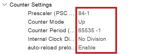](https://bookstack.roboteamtwente.nl/uploads/images/gallery/2026-04/lTKafbeelding.png)**NOTE:** -1 for prescaler and counter period because of 0 index counting
To fully configure the PWM generation, we have to set the above parameters. The **prescaler** has to do with the clock configuration. You want to set the prescaler **equal to the amount of MHz in the clock configuration**, because we will divide the clock frequency by the prescaler! Here, we have set the **clock speed to 84 MHz** (see [Clock configuration](#bkmrk-clock-configuration "Clock configuration")), so we set the prescaler to 84 (-1) as well. This way we work with **1MHz** in calculating the counter period for the wished for PWM frequency (see below). [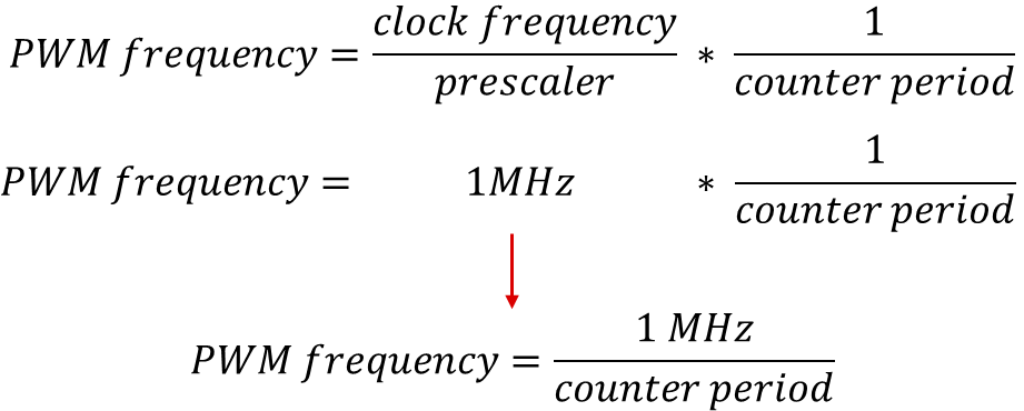](https://bookstack.roboteamtwente.nl/uploads/images/gallery/2026-04/xC5afbeelding.png)**NOTE:** the counter period parameter uses the ARR (AutoReload Register). Those terms are used interchangeably in online sources.
As of now, the counter period is at **65535**, which is the maximum value for an unsigned 16bit integer. This results in a PWM frequency of 1098Hz. The **frequency** of PWM should be suitable for the motor you are using. We can change this value later. For more information on PWM see [resource 1](https://deepbluembedded.com/stm32-pwm-example-timer-pwm-mode-tutorial/). ### 2) Clock configuration The board can be optimized to run at a higher frequency than is preconfigured. You can set the system clock to work at **84 MHz** by setting any of the right-hand clocks in the clock configuration menu to 84. The program then auto calculates the settings for the system, also see [resource 2](https://youtu.be/zHWvFchXhvw?si=nGj-vzkVCszjHonW). [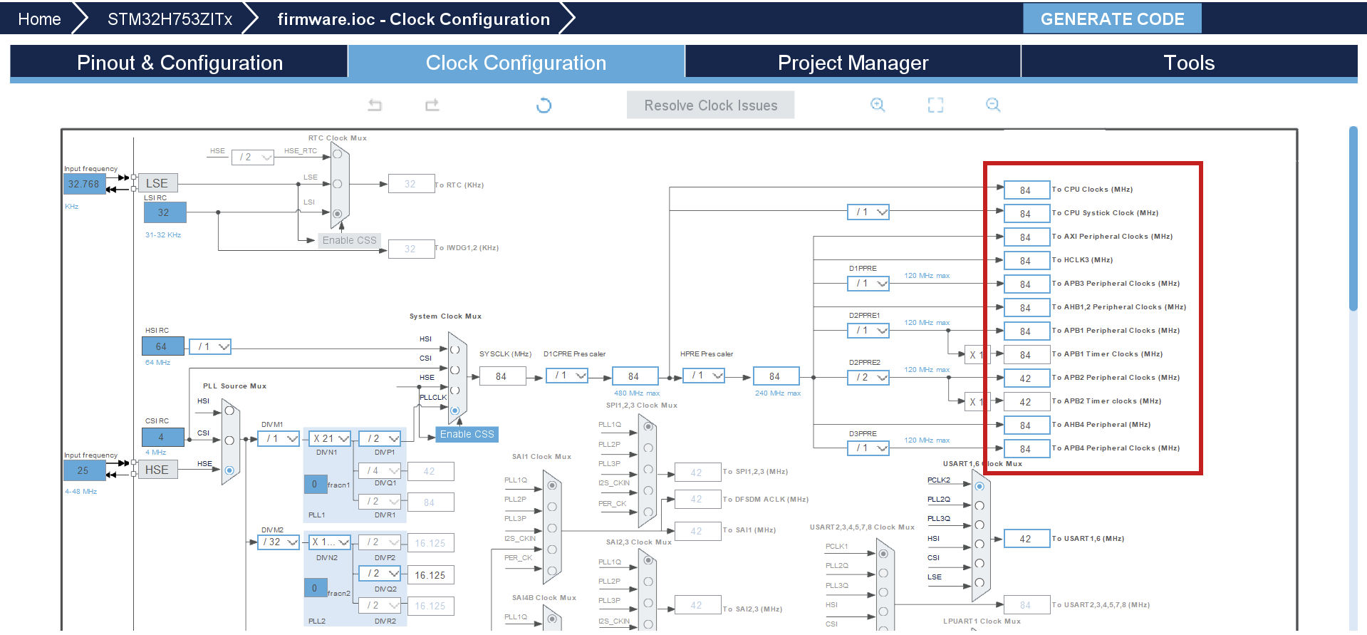](https://bookstack.roboteamtwente.nl/uploads/images/gallery/2026-04/oysafbeelding.png) --- ## **Resources** 1. [Deepbluembedded.com: STM32 PWM Output Example Code (PWM Generation Tutorial)](https://deepbluembedded.com/stm32-pwm-example-timer-pwm-mode-tutorial/) 2. [YouTube: STM32 Beginners Guide Part3: PWM, TIMERS, Frequency and Duty Cycle. LED Dimming with PWM example.](https://youtu.be/zHWvFchXhvw?si=nGj-vzkVCszjHonW) # Stepper library ## **Purpose** ## **CubeMX** ### 1) PWM**NOTE:** If you are new to PWM, first take a look at [Example PWM generation](https://bookstack.roboteamtwente.nl/books/robotic-arm/page/example-pwm-generation "Example PWM generation"), it is more in depth
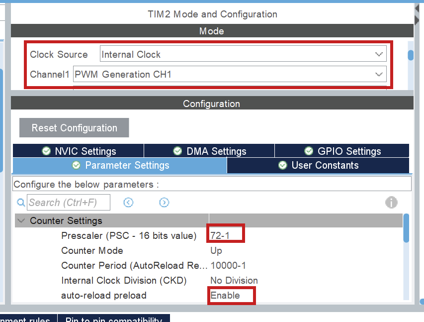**For each stepper**, enable pwm on channel 1. This is done by setting `Clock Source = Internal Clock` and `Channel 1 = PWM Generation CH1`.**NOTE:** Each pwm output for each stepper needs a **separate timer**. Right now, it is hardcoded that **PWM uses Channel 1**, so only use Channel 1!
The following parameters are important: - `prescaler` The **prescaler** has to do with the clock configuration. You want to set the prescaler **equal to the amount of MHz in the clock configuration**, because we will divide the clock frequency by the prescaler! (On the board right now, the clock speeds is set to 72MHz.) This way we work with **1MHz** in calculating the frequency and duty cycle. - `auto-reload preload` I lowkey don't know what this does, just enable it to be safe. ### 2) DMA Now, you have to set up the DMA for the same timer/channel. This is in the `DMA settings` tab. [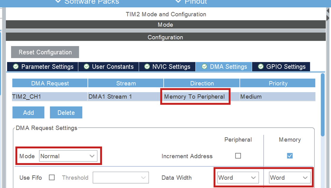](https://bookstack.roboteamtwente.nl/uploads/images/gallery/2026-05/VPKafbeelding.png) Set the following parameters: - `DMA Request = TIMx_CH1` This is the timer and channel which will be using DMA. **Make sure this is on channel 1, as stated above!** - `Stream` This can be any of the available streams. - `Direction = Memory to Peripheral` **Important!** Because we will be using DMA to transfer PWM signals from the code (memory) to the pin (peripheral) it needs to be set this way. - `Priority` This can be set to any level, but note that it is advisable to put **all steppers to the same priority**. I don't know (and am not responsible for) what happens if they are different. - `Mode = Normal` In normal mode, DMA transfers the buffer from memory **ONCE** and then remains at the last sent value (remember this, it is important later). See [resource 1](https://controllerstech.com/pwm-in-stm32/). - `Data width = Word` This is the width of the values we will be sending. Since the values we will be sending are used to fill the CCR register, we will set this to word (uint32\_t size). Half word would be for 16 bit registers. ### 3) GPIO pins Set 2 pins to GPIO\_Output by clicking on them in the CubeMX UI. One of these will be used for the direction pin and another for the enable pin. //TODO: add driver resource ### 4) Clock Configuration For PWM it really doesn't matter at what speed you set the clock. The only thing that matters is that the prescalar is set to the same amount. So if your clock speed is 72, set it to 72-1, if your clock speed is 84, set it to 84-1. --- ## **Code** ### 1) Public Methods ### 2) Private Methods ### 3) Example ## **Resources** 1. [Controllerstech: STM32 PWM Output: Generate PWM Signal with & without DMA](STM32%20PWM%20Output:%20Generate%20PWM%20Signal%20with%20&%20without%20DMA) # Main # All resources