Surface Sampling Container
Mechanical
1. List of Requirements
1.1 Functional Requirements
- The system shall store regolith, Mars powder, and rock/probe samples in 2–3 separate compartments, keeping sample types isolated from collection through storage.
- The robotic arm shall use a scoop tool to collect sample material from the surface and deposit it onto the container's weighing platform.
- Once loaded, the container shall weigh the total collected sample mass.
- If the measured mass meets or exceeds the minimum threshold (100 g), the lid shall open via the motor, and the material shall be deposited into the appropriate compartment; the lid shall then close and lock automatically via magnetic caps mounted on the lid and container base.
- If the measured mass falls below the threshold (100 g), the motor shall actuate to open the container and reject the sample rather than store it.
1.2 Technical Requirements
- Compartment and lid actuation shall be motor-driven.
- The full assembly shall fit within the housing dimensions defined for the system.
- The lid shall open to a maximum of 90 degrees.
- Probe mounting shall follow the dimensions specified in the Mars Rover Competition manual.
- A piezoelectric sensor shall be integrated for mass measurement, mounted directly to the chassis.
- The system shall be fully 3D-printed to satisfy overall weight limitations.
- The weighing platform shall be constrained to a single degree of freedom in Z-translation, ensuring the platform remains stationary during measurement for accurate readings.
1.3 Performance Requirements
- The locking mechanism shall maintain a secure seal under vibration and transport loads.
- Each sampling operation shall require a minimum viable sample mass of 100 g.
- If the measured mass is below 100 g, the system shall reject the sample automatically by opening the container rather than storing the material.
2. Detailed description of the system and its subsystems
2.1 Sensing Subsystem — Weighing & Mass Detection
A piezoelectric sensor is used for mass measurement, mounted directly to the chassis beneath the weighing platform. Piezoelectric sensors were chosen for their compact form factor relative to the sensitivity required, fitting within the limited internal space of the container assembly. The weighing platform itself is constrained to a single degree of freedom in Z-translation, keeping the platform stationary in all other axes during measurement to ensure accurate, repeatable readings.
FInd the video attached for the sensor: Pizoelectric Working Principle

2.2 Actuation Subsystem — Motor and Gearbox Selection
Torque requirement calculation:
The torque required to open the lid was calculated at approximately 1.3 Nm. Applying a safety factor to account for friction, material tolerances, and dynamic loading during operation, the design torque requirement was set at 1.6 Nm.
Motor selection reasoning:
Motor research indicated a clear trade-off between torque output and motor weight — higher-torque motors carry proportionally more weight, which conflicts with the system's overall weight constraints. To resolve this, a lower-torque, lower-weight motor was selected, with the torque deficit compensated by a gearbox rather than oversizing the motor.
- Motor chosen: NEMA 17 servo motor, rated torque of 0.4 Nm. [[Motor Link]
- Gearbox ratio: 1:4, giving an effective output torque of 1.6 Nm, matching the design requirement including safety factor
This approach kept the actuation subsystem lightweight while still meeting torque demand — prioritizing a compact, low-mass solution over a single oversized motor.
2.3 Mechanical Transmission — Linkage and Hinge Mechanism
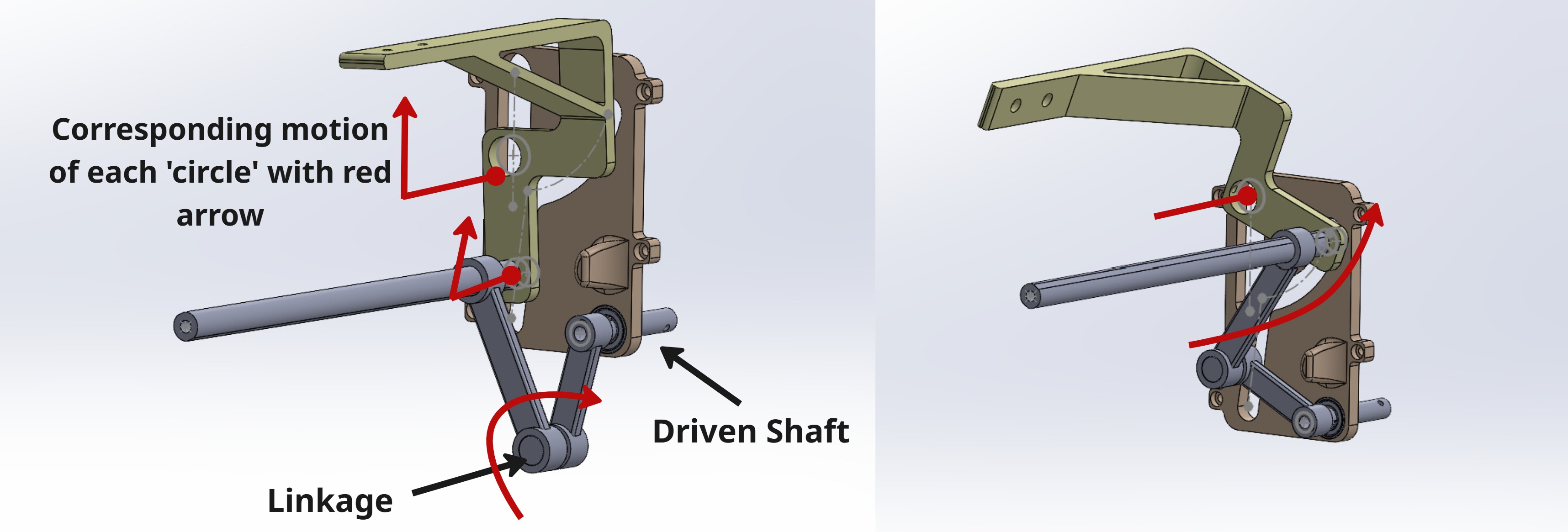
Power from the motor is transmitted through the gearbox to a shaft, which drives the linkage mechanism connected to the lid hinge. The motion sequence is as follows:
- The output shaft transmits torque to the linkage.
- The linkage first drives a Z-axis translation of the hinge (yellow part).
- This translation is converted into rotation via the hinge, which is connected on both sides through shafts that transmit torque from the linkage to the hinge mechanism.
- A slotted connection at the hinge accommodates the transition between translational and rotational motion, allowing the lid to lift and rotate open up to 90 degrees.
2.4 Compartment Subsystem
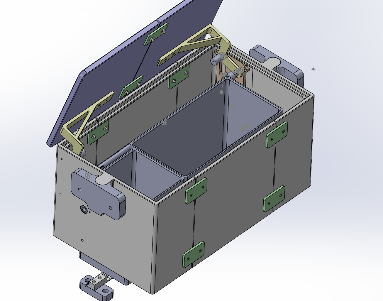
The container houses 2–3 separate compartments, each dedicated to a distinct sample type (regolith, Mars powder, rock/probe samples) to prevent cross-contamination between materials from collection through storage. Compartment access is coordinated with lid actuation, so material is only deposited once the corresponding compartment is aligned and the lid is open. As shown, compartments are sized to their contents — smaller for regolith and larger for rock samples.
2.5 Locking Subsystem
Once a sample is deposited and the lid closes, the container locks automatically via magnetic caps mounted on the top of the lid and the base of the container. This passive locking mechanism (locked by default) ensures the seal is maintained under vibration and transport loads without requiring continuous motor engagement, reducing power consumption during transit. As shown, the magnetic caps are mounted on the inner surfaces of the lid and the container base from both sides.

3. Operation of the system
Sample collection follows with combining the robotic arm, the weighing platform, and the lid actuation mechanism. Each sample is measured before storage, ensuring only material meeting the minimum mass requirement is retained. The operational sequence is as follows:
- System initialization. On startup, the lid is closed and locked by default via the magnetic caps, and the weighing platform is in a ready state.
- Sample acquisition. The robotic arm, using the scoop tool, collects a sample (regolith, powder, or rock/probe material) from the surface.
- 3. Sample placement and measurement. The arm positions the scoop over the container and deposits the sample onto the top of the lid. The weighing system, mounted at the base of the container, measures the sample's mass through the transmitted load.
- Mass evaluation. The measured mass is compared against the minimum threshold of 100 g.
- Accepted sample. If the threshold is met, the arm moves the scoop aside, the motor actuates to open the lid up to 90 degrees, and the sample is poured into the compartment corresponding to its material type. The motor then closes the lid, which re-locks automatically via the magnetic caps.
- Rejected sample. If the threshold is not met, the motor actuates to open the container and discard the sample without storing it, and the system returns to a ready state.
- Cycle repeat and task completion. Steps 2–6 repeat for each subsequent sample until all compartments are filled or the sampling task is marked complete, at which point the lid remains closed and locked for transport.
4. Materials + Manufacturing
The full system was 3D printed, using PETG for all parts. The base was split into three separate pieces and printed on a Qidi printer, while the remaining components were distributed across different printers to parallelize production.
Assembly of the base pieces relied on dedicated bolt-and-nut connection features printed into the parts themselves, allowing the three sections to be joined together. The remaining components were assembled using nuts, bolts, and washers, with threaded inserts used at critical joints to prevent tipping.
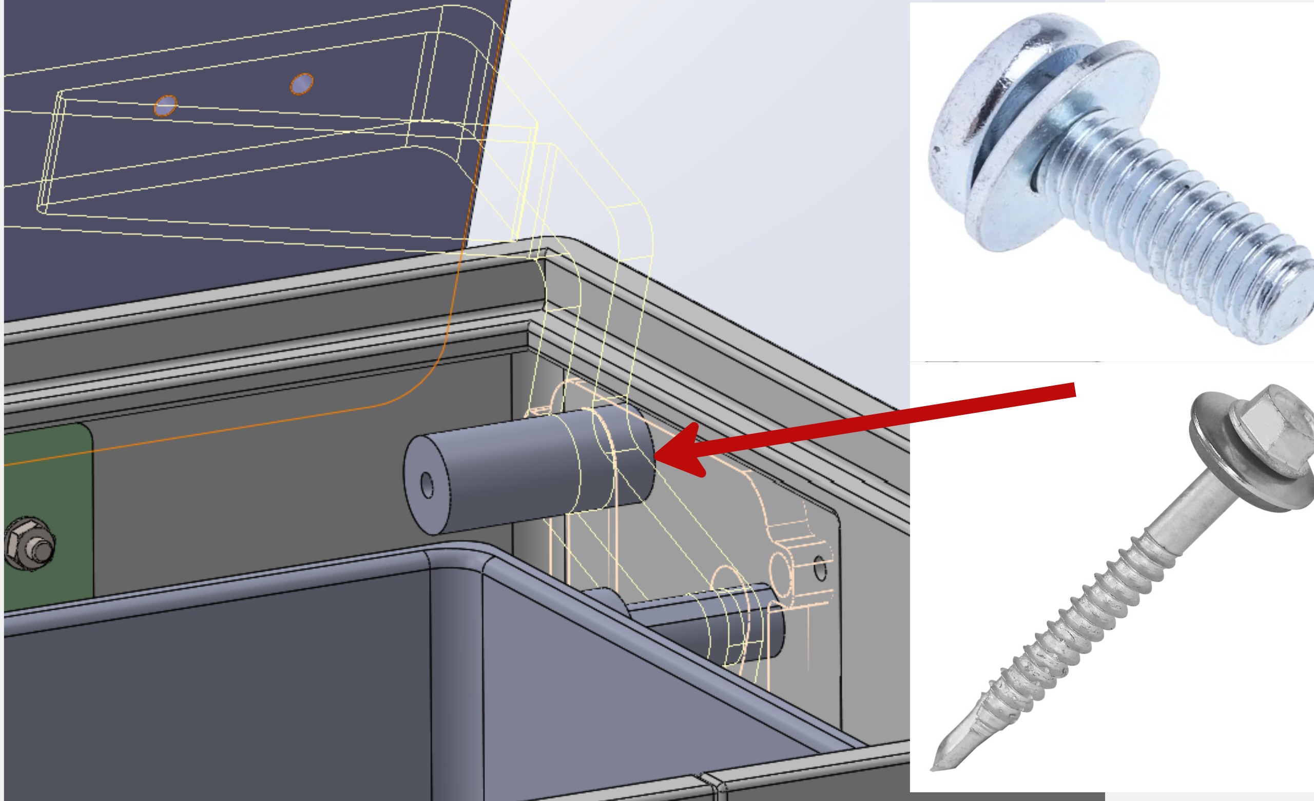
At the hinge, threaded inserts secure the connection with the slots, paired with a washer and bolt/screw to keep the hinge aligned and stable. Each hinge pin is a cylindrical shaft with a central hole, into which a threaded insert is heat-set (soldered). A bolt threads directly into this insert, and a washer with a radius larger than the slot width is placed under the bolt head — so once tightened, the washer cannot pass through the slot, retaining the pin in place and preventing it from tipping during operation.
The main shaft uses the same approach — internal threaded inserts combined with a screw tube — assembled with a washer to prevent the shaft from tipping.
5. Currently faced issues
The following issues have been identified in the current version of the system and remain unresolved:
- Shaft torque transmission. The 3D-printed shaft spanning the full width of the container is poorly suited to transmitting torque, particularly given its length; this directly affects the reliability of the linkage drive.
- Motor placement and torque distribution. Given the container's length, there is a risk that even a rigid shaft won't distribute torque evenly along its length, potentially causing uneven lid actuation — one side lifting higher than the other.
- Untested motor-driven motion. The system has not yet been tested with the motor installed, so the actual range of motion, its limitations, and areas for improvement remain unknown.
- Unverified impact protection. Memory foam padding has not yet been implemented, so it's unconfirmed whether PETG can withstand impact from falling rocks of varying weights.
- Unvalidated mass sensor. The piezoelectric sensor remains a design concept only and has not been tested.
- Incomplete scoop design. The scoop still needs to be designed to handle both regolith and rocks, including a spherical or square handle geometry for easier grip.
- Long print times. Base components in particular require excessive printing time, slowing iteration and production.
6. Ideas for future improvements
- Rigid shaft replacement. Replace the 3D-printed shaft with a purchased rigid shaft, since the printed version proved inadequate for torque transmission.
- Centralized motor and gearbox placement. Relocate the motor and gearbox to the middle of the container to achieve more even load distribution along the shaft.
- Load isolation. Isolate the linkage system — and the motor — from external loads to prevent impact or structural forces from affecting the drive train.
- Dual-motor configuration. Consider a second motor to reduce gearbox size, with corresponding adjustments to gear ratios and module selection from both sides accordingly.
7. Conceptualization
The Surface Sampling Container was built to collect, check, and store different Mars surface materials — regolith, Mars powder, and rock/probe samples — while staying within the weight and size limits. The main goals were to keep sample types separate, check each sample's weight before storing it, and keep the container sealed during transpor.
Weight was the biggest limit on the whole design. Instead of using one large, heavy motor, a small NEMA 17 motor with a 1:4 gearbox is used to reach the torque needed to open the lid. This kept the actuation system light while still meeting the torque requirement. For the same reason, the whole system was 3D-printed in PETG to save weight, even though this later caused problems with the shaft's strength.
The linkage-and-hinge mechanism was chosen so one motor could do two things: lift the lid up and then rotate it open, instead of needing separate motors for each motion.
The magnetic locking caps were chosen so the lid stays closed and sealed on its own, without the motor needing to hold it shut. This saves power during transport.
The weigh-before-store step was added so the system only keeps samples that are heavy enough to be useful. If a sample is too light, it gets rejected right away instead of taking up space in a compartment.
Overall, every major choice in this design favored staying light and simple over making the system as strong as possible.