Drive system
Mechanical
Hello
world
Electrical
Control
Overview
General structure
The general structure of how the control system is made, tested, and deployed works like this:
The control system is made using Simulink, using mostly the base functionality to calculate the needed values for different parts of control. Once the general control system is implemented, it is either tested directly in Simulink, mostly using different parts from the Simscape suite to simulate the hardware, or it can be tested by generating the code, and using that code in a separate, more high level simulation program like Gazebo or Webots.
The deployment is mostly managed by the embedded team, as once the code is generated, it can be used in whatever is necessary for the embedded team.
Required software
MATLAB Simulink with the following add-ons:
- Embedded Coder
- Simulink Coder
- Simulink Compiler
- MATLAB Coder
- MATLAB Compiler
Code generation
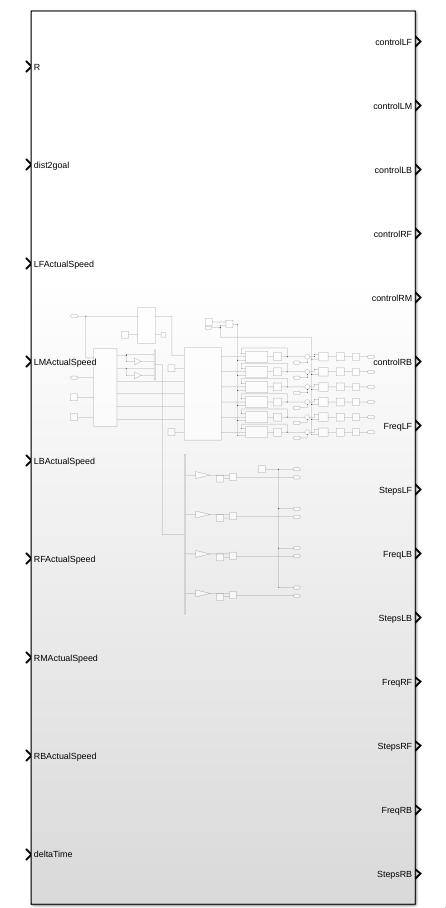
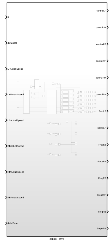
In general the code is generated from Simulink blocks, where all the control has to do is done inside this one block:
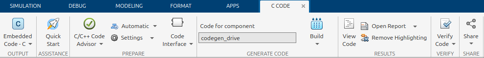
To be able to generate C code for the STM32's you will first need to activate the embedded C coder, which can be done by clicking on the apps tab in the top bar, and then searching for C embedded coder in the apps bar.

After the embedded C coder is active, a new tab called C CODE appears, where you now have to press the quick start button to start the code generation process:
When in the quick start menu, the only critical options for this project are to set the system which gets generated to the main control block of this project, and to set the word size to be the same as the ones from the STM32.
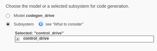
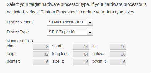
The rest of the settings work best on the default option, but can be changed if deemed necessary.
Manual control
Automatic control
Overview
In general, the job of the control system is to turn high level instructions from the software system, and turn them into instructions for the hardware. This is done by having a distance to a goal, a turning radius, and a deltaTime as an input, and turning those into control signals for the motors:
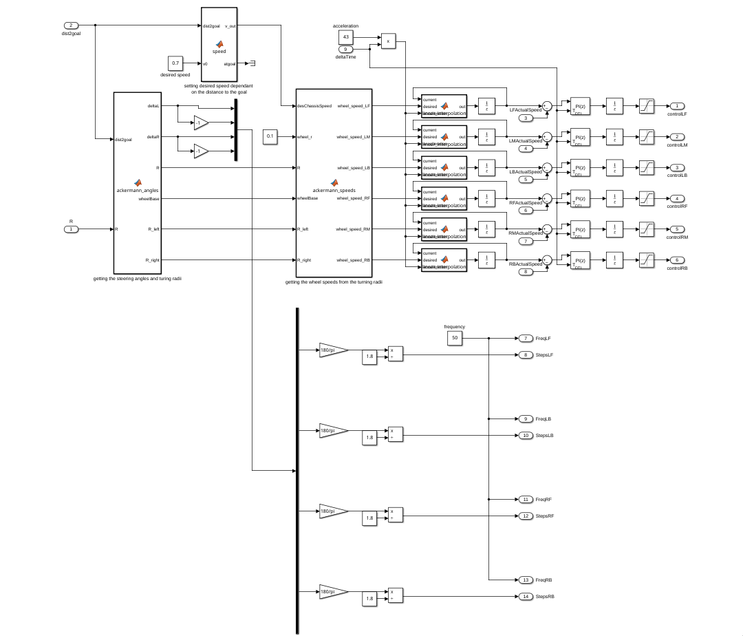
This is done in several steps.
Determining current desired speed
To determine what speed the rover should move at this moment, the distance to the goal is used to decide how fast the rover should move, which in general means, closer to the goal = move slower, and if we are really close, stop moving completely. If the rover is not close to the goal, it will try to move at v0 speed.
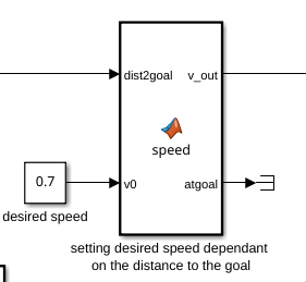
The function simply works like this:
function [v_out, atgoal] = speed(dist2goal, v0)

%slow down if close to goal
if dist2goal <= 1
    v_out = 0;
    atgoal = 1;

%stopping if the rover is close to the target
elseif dist2goal <= 2
    v_out = v0 * 0.5;
    atgoal = 0;

%keeping cruising speed if not close to goal
else
    v_out = v0;
    atgoal = 0;
end
Ackermann steering
Getting the necessary angles that the steering motors need to make is done by calculating the Ackermann steering angles that equate from the given turning radius and distance to the goal.
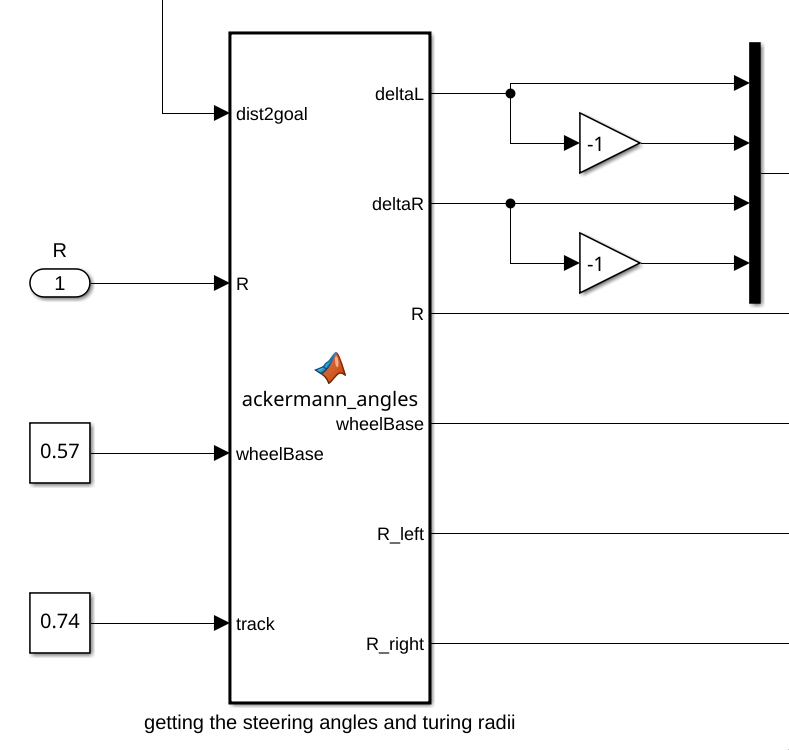
deltaL and deltaR are equal to the angles that the left and right steering motors need to make, which are sent to the steering control.
This function also outputs the turning radius of the right and left wheels of the rover.
The function works like this:
function [deltaL,deltaR,R,wheelBase,R_left,R_right] = ackermann_angles(dist2goal,R,wheelBase,track)
    % Function to compute ackerman steering angles from a bicycle steer angle.
    if R == 0
        alpha = 0;
    else
        alpha = dist2goal/R;
    end

    R = abs(R);

    if alpha < 0
        R_left = (R+track/2);
        R_right = (R-track/2);
        deltaL = atan(wheelBase/(R_left));
        deltaR = atan(wheelBase/(R_right));
    elseif alpha > 0
        R_left = (R-track/2);
        R_right = (R+track/2);
        deltaL = -atan(wheelBase/(R_left));
        deltaR = -atan(wheelBase/(R_right));
    else
        deltaL = 0;
        deltaR = 0;
        R_left = R;
        R_right = R;
    end
end
Ackermann speeds
Using the data coming from the previous function, as well as a wheel radius and motor gear ratio, the speeds needed by the motors are calculated.
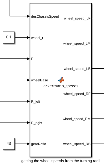
Internally the function works like this:
function [wheel_speed_LF,wheel_speed_LM,wheel_speed_LB,wheel_speed_RF,wheel_speed_RM,wheel_speed_RB] = ...
          ackermann_speeds(desChassisSpeed,wheel_r,R,wheelBase,R_left,R_right,gearRatio)
if R > 0
    wheel_speed_LF = (desChassisSpeed/wheel_r)*sqrt(R_left^2 + (wheelBase/2)^2)/R;
    wheel_speed_LM = desChassisSpeed * R_left/(R*wheel_r);
    wheel_speed_LB = (desChassisSpeed/wheel_r)*sqrt(R_left^2 + (wheelBase/2)^2)/R;
    wheel_speed_RF = (desChassisSpeed/wheel_r)*sqrt(R_right^2 + (wheelBase/2)^2)/R;
    wheel_speed_RM = desChassisSpeed * R_right/(R*wheel_r);
    wheel_speed_RB = (desChassisSpeed/wheel_r)*sqrt(R_right^2 + (wheelBase/2)^2)/R;
else
    wheel_speed_LF = desChassisSpeed / wheel_r;
    wheel_speed_LM = desChassisSpeed / wheel_r;
    wheel_speed_LB = desChassisSpeed / wheel_r;
    wheel_speed_RF = desChassisSpeed / wheel_r;
    wheel_speed_RM = desChassisSpeed / wheel_r;
    wheel_speed_RB = desChassisSpeed / wheel_r;
end
    wheel_speed_LF = wheel_speed_LF * gearRatio;
    wheel_speed_LM = wheel_speed_LM * gearRatio;
    wheel_speed_LB = wheel_speed_LB * gearRatio;
    wheel_speed_RF = wheel_speed_RF * gearRatio;
    wheel_speed_RM = wheel_speed_RM * gearRatio;
    wheel_speed_RB = wheel_speed_RB * gearRatio;
end
Control signals
DC motors
After getting all the angles and speeds needed for the rover to make a certain movement, the signals get sent to the motor drivers/controllers in a way that they can use them.
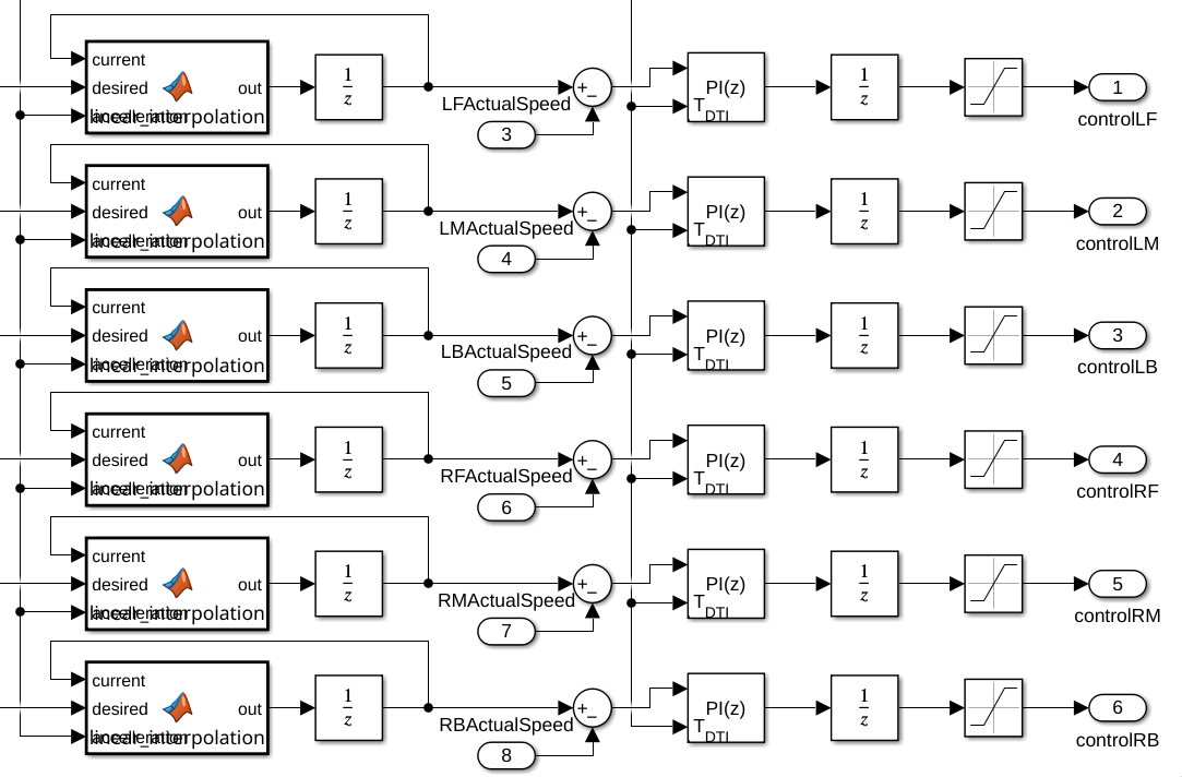
The DC motors are controlled by first sending the desired speed into a linear interpolation function block, which just makes the desired speed change like a linear function, instead of as a stepping function gradually changing the speed to limit the amount of amps being pulled at startup.
function out = linear_interpolation(current, desired, accelleration)
if current < desired
    current = current + accelleration;
end
if current > desired
    current = current - accelleration;
end

out = current;
After this, the linearly changing desired speed will be compared with the actual speed of the motors and the final speed will be controlled using PI controllers which are saturated to stay between -5V and 5V.
Stepper motors
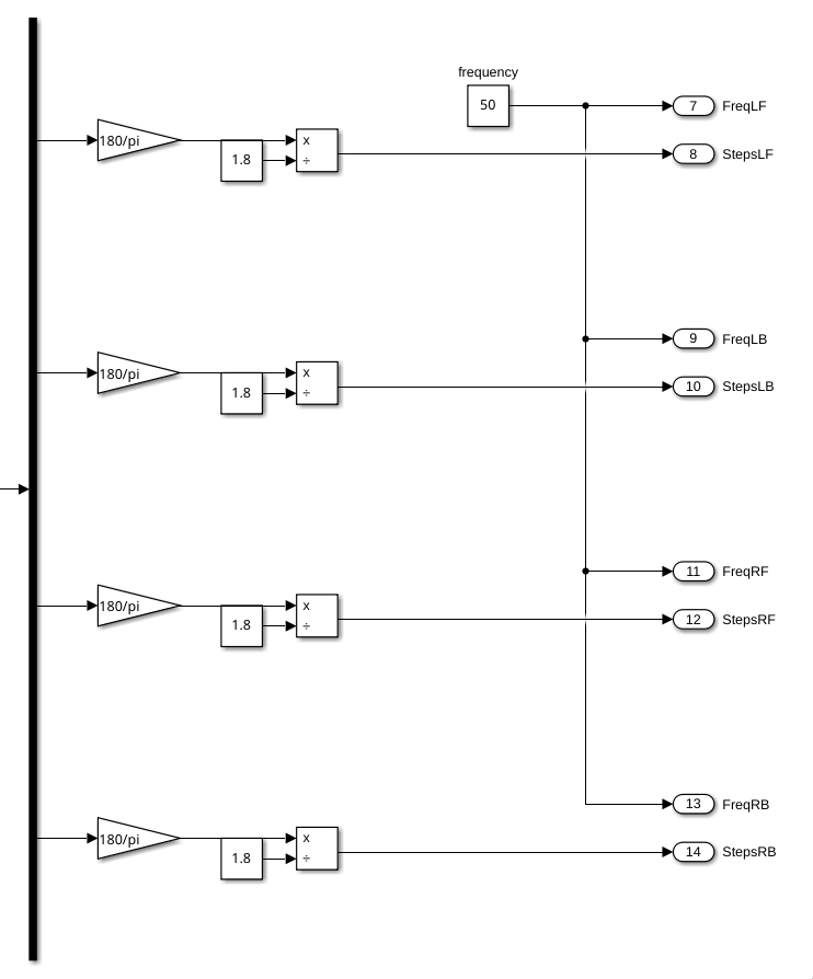
Due to the limitations of Simulink, making the stepper motors move is done using PWM signals coming from the STM32 microcontrollers. The control system only gives the desired position of the stepper motors in terms of steps, and a frequency at which the PWM signal pulses, which in this case is just a constant value.
The sending of the PWM signals is handled by the embedded team.
Simulation
Simulation of the drive system
Simulink
Overview
The simulation is done using a main control block called control_drive, which as inputs gets a turning radius, a distance to goal, and a deltaTime. From these inputs, different control signals are calculated for the different motors, using simulated DC motors as well as stepper motors. Both the types of motors send the relevant feedback to the control block using goto blocks.
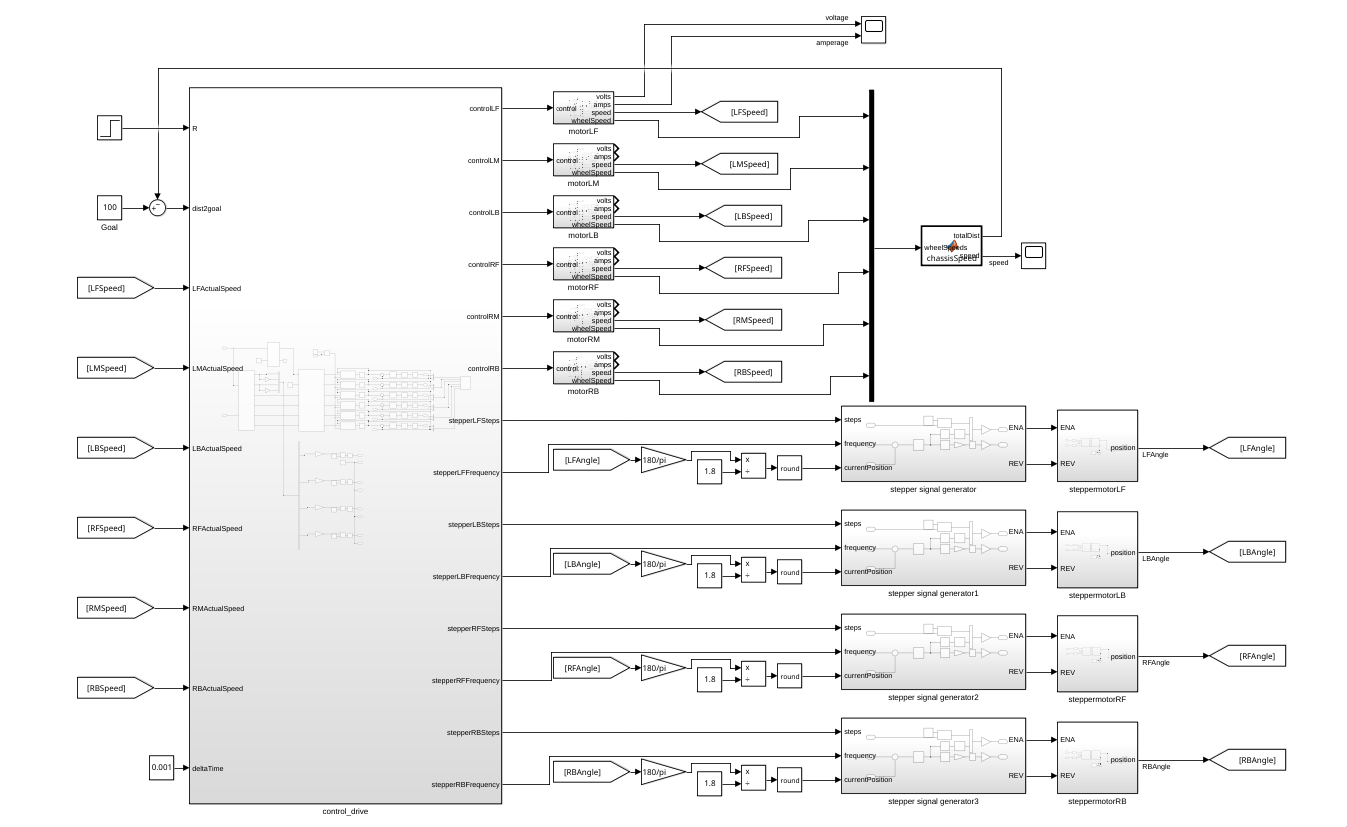
The driving motors are connected directly to the control block, processing the control signal directly.
The steering motors are connected to pulse generators to send instructions.
Driving motors
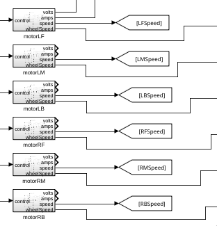
The driving motors are simulated as 6 motor blocks that have a control signal as input, and as outputs a speed from the motor, speed from the wheel, motor voltage and amperage.
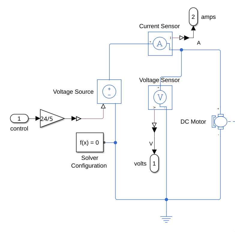
The driving motors are simulated with Simscape components, at first using a gain block with a 24/5 gain to what the motor driver would be doing (turning a 0V-5V signal to a 0V-24V signal). This value is sent to Voltage Source, which sends sends a voltage to a DC motor to create a rotational force.
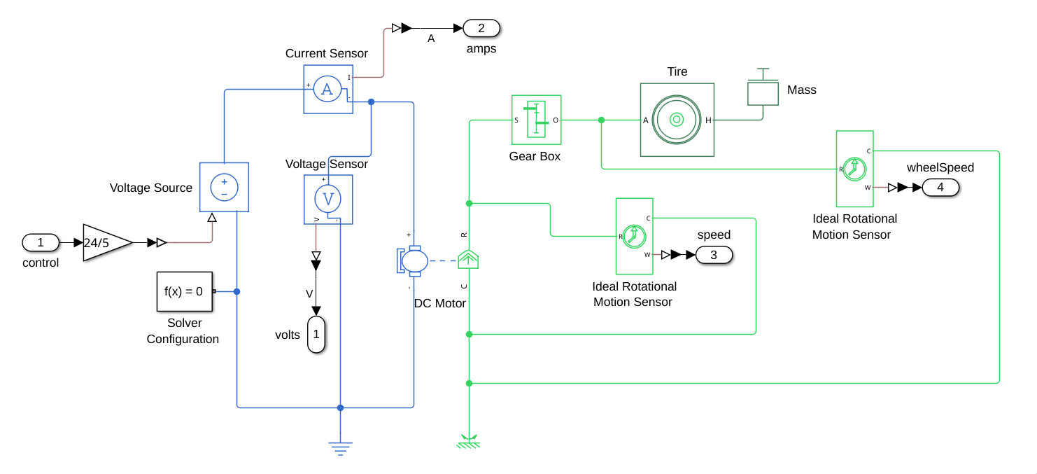
This voltage is also read by a voltage and current sensor to get the expected power values at different speeds.
The speed of rotation is measured both before, and after the connection to the gearbox:
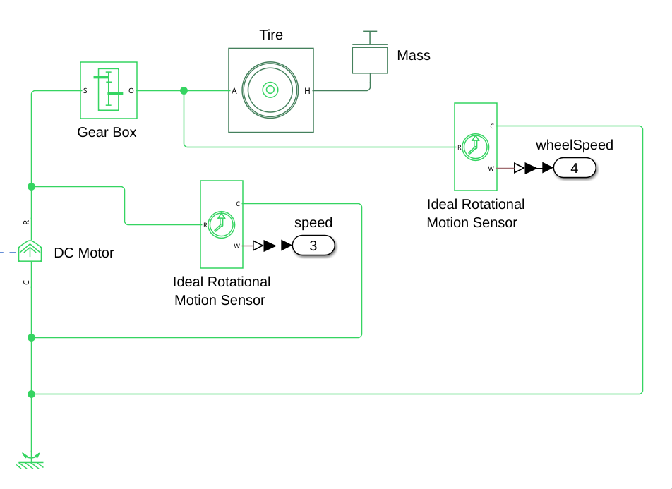
This is to get both the speed that would be read by the hall-sensors in the actual motors, as well as the speed going to the wheels to do further calculations with. The rotation of the motor after the gearbox is also connected to a tire with a mass equal to 1/6th of the mass of the rover.
Six of these motors are simulated, with the motor speed being used as feedback for the control system, and the wheel speed being used to calculate the actual speed of the rover.
Steering motors
The steering motors are connected to the control by connecting them to pulse generators that send signals to the stepper motors to set them to the correct positions.
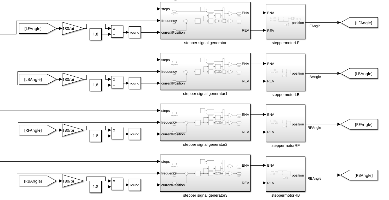
The calculation before the current position enters the signal generator is used to convert the motor angle from radians to stepper motor steps. This is done to be able to control the stepper motors with the amount of steps that have been/ need to be taken to get to a certain position.
The stepper motor blocks themselves contain a simple stepper motor with a stepper motor driver, reading the final angle the motor moved to as output.
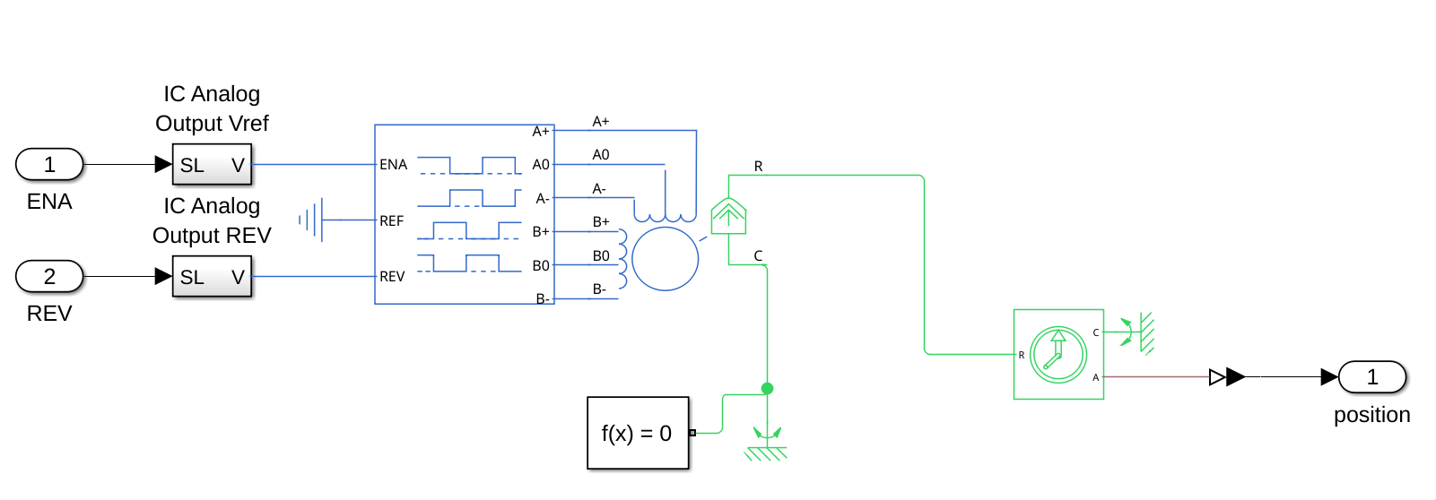
To control the motors, an ENA and REV signal are sent from pulse generator blocks (REV specifies the direction that the motor spins and ENA is a pulse signal activating the steps):
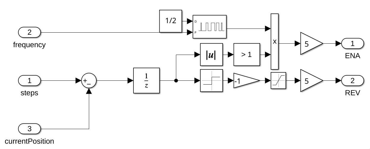
This is done to simulate the behaviour of the PWM signals that will be sent by the STM32 microcontroller.
Webots
Embedded
Getting Started
This page: structure of this subsystem
components/driving_board folder contains 4 libraries:
- firmware
- motor
- parser
- simulink
Firmware contains the generated CubeMX code. Don't edit this after generating, it will be rewritten after you generate again.
NOTE: do make sure that after generating your code in CubeMX, you run the post generation script. You can set a post generation script in CubeMX itself. However, if you use Windows run: scripts/post_code_generation.bash, if you use Mac run: scripts/post_code_generation_mac.bash
The Simulink folder contains code generated by the control team, and it shouldn't be modified by embedded. This code is not used on the embedded side, but it provides a clear reference for the type of input we give to control algorithm and the output we receive from it.
In control.h, struct ExtY gives the external outputs and ExtU is the struct for external inputs.
src/driving_board contains main.c
This is the code that runs when we build and update to the board by pio. Main includes multiple threads for some tasks that need to run concurrently.
ERC-Protobufs/components/driving_board contains protobuffers for this subsystem
Protobuffers are used to send information to software and debugging board and receiving information from software.
Motor Folder
components/driving_board/motor
All of the motor functions in this folder are called in Main
BLDC Motors:
They are used to control the speed of the rover.
bldc.c contains:
The set_bldc_pwm() method. This methods scales the control signal value calculated from control code and adjust the pwm duty cycle outputted by the STM32 accordingly.
Stepper Motors:
stepper.c contains:
The set_stepper_pwm() method. This methods scales the control signal value calculated from control code and adjust the pwm frequency outputted by the STM32 accordingly.
Encoders:
read_encoder.c contains:
The read encoders() method. This method reads encoder values of encoder angle, voltage generated and rpm.
Parser Folder
components/driving_board/parser
This page: structure of message encoding in parser.c
The encoding logic includes:
copy_motor_to_pb():
Copies each motor from internal MotorDiagnostic struct into protobuf MotorInformation.
DBMDiagnosticsEncode():
Encodes full diagnostics data into a protobuf message.
This function: Initializes the protobuf message Copies board state Copies all 10 motors into the protobuf structure Calls pb_message_encode to serialize data
The diagnostics message contains 10 motors:
front_left, middle_left, back_left, front_right, middle_right, back_right, steering_front_left, steering_back_left, steering_front_right, steering_back_right,
Each motor is copied using a loop into the protobuf message.
message_add_envelope():
This method wraps a protobuf message into a PBEnvelope using the same pb_message_encode function.
It: Takes a populated protobuf message (e.g. DrivingBoardDiagnostics) Initializes a PBEnvelope Sets the correct oneof field (e.g. drive_diag) Calls pb_message_encode on the envelope struct Returns encoded envelope buffer and length
Main
src/driving_board/main.c
contains the main firmware entry point and runtime logic for the driving board. The system is built on FreeRTOS (CMSIS-RTOS v2) and runs multiple tasks concurrently.
Initialization
init_board()
This function initializes the full system before starting the scheduler.
It:
- Configures MPU and cache
- Initializes HAL and system clock
- Initializes GPIO, timers, and UART logging
- Initializes control algorithm (control_initialize)
- Initializes Ethernet and MAC filtering Creates FreeRTOS tasks Starts PWM and encoder peripherals
- Starts the RTOS kernel. After this, the scheduler takes over.
Tasks
The system runs 3 main threads:
MainTask
This task handles: Ethernet communication Diagnostics message creation and sending Periodic data updates
Example Flow For Sending A Message:
- Initialize UDP Fill DiagnosticsData using FillDiagnostics
- Encode using DBMDiagnostics
- Encode Send encoded data over Ethernet
- Free allocated memory after sending Also sends test UDP and raw Ethernet messages.
PwmTask
This task runs the control loop.
It:
- Calls control_step() from control module(Simulink folder)
- Reads outputs from rtY
- Updates motor PWM using set_bldc_pwm Runs periodically (1 ms)
DrivingEncoderTask
This task processes encoder data.
It:
- Reads timer counters
- Calculates: revolutions radians (position) rpm (speed)
- Populates motor data (rpm, voltage, angle).
- Updates global variables used in diagnostics
- Runs every 100 ms