Mechanical
Introduction
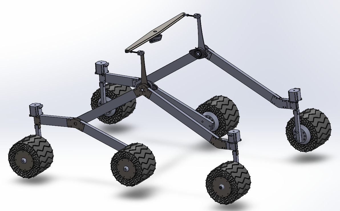 The entire mechanical side of the drive system consists of 4 main subsystems, the suspension, turning system, the motor subassmebly and finally the wheels themselves. The Drivetrain was design and developed in conjunction with the PD&D (Product Design and Developement) minor project. With this, a report was also made where most (but not all) design rational exists. It mainly focuses on the wheel and motor subassembly design, rational, and performance validation through simulation. The suspension and the turning system is the secondary focus on the report due to time constraints and also not wanting the report to be too long. This can be found in the following location:
G:\Shared drives\RoboTeam Twente Main Drive\RTT2025-2026\04. Subteams\08. Minor Assignment\Reports 2025-2026.
or alternatily through this link:
Design and Development of a Rover Drivetrain
NOTE: The current rover assembly uses the old motor subassembly as this was a last minute change due to motor suppliers, and changing the entire assmebly is quite some work as it requires wierd SOLIDWORKS mirroring features that do not play nice with ISO components like, nuts, bolts, gears, etc.
Suspension
The rover utilizes a passive rocker-bogie suspension architecture coupled with a top-mounted differential rocker mechanism. This mechanical design allows all six wheels to maintain continuous contact with uneven terrain without relying on active electronic stabilization or heavy spring-damper assemblies.
System Architecture & Components
The suspension relies on purely kinematic links to distribute weight evenly and isolate the central payload chassis from violent pitching when traversing obstacles.
- Rocker-Bogie Side Linkages: Two independent side linkages (left and right). Each main rocker pivots relative to the chassis, while the rear bogie links pivot relative to the main rocker, allowing the wheels to contour over rocks and dips.
- Chassis Pivot Mounting Assemblies:
- Located on the left and right side plates of the chassis frame to serve as the primary structural attachment points for the main rockers.
- Utilizes heavy-duty bearings housed in a bearing houising unit. These housing units are then bolted to the side of the chassis.
- The main tube that runs into the housing unit is clamped to the rest of teh suspension system using locking bushings. These bushings, when tightened, shrinks radius of the inner cutout, clamping down on the tube. Two lasercut parts flank either side of the bushing, connecting everything together.
- Top-Mounted Differential Rocker Arm:
- A rigid cross-bar mounted horizontally over the top deck of the chassis, rotating around a central vertical plane pivot pin.
- Connects the left and right main rocker arms using vertical tie-rods (turnbuckles) with spherical rod ends (heim joints). These rod ends can both piviot up and down, and side to side, providing the degrees of freedom needed to make this system work.
- Enforces anti-phase motion between the left and right suspension sides: as one side lifts over an obstacle, the top rocker pivots and forces the opposite side downward.
Design Rationale & Kinematic Mechanics
More specifics of the construction can be found in the drive system report
- Equalized Wheel Loading & Traction: In conventional spring suspension systems, climbing a large step severely compresses one corner, shifting the vehicle's center of mass and reducing ground pressure on the remaining wheels. The passive rocker-bogie geometry mechanically balances vertical loads so that all six wheels share traction equally, minimizing wheel slip on loose terrain.
- Chassis Pitch Averaging (Differential Kinematics): Without a differential linkage, the chassis body would freely tilt to extreme angles whenever a single side encountered an obstacle. The top-mounted differential arm acts as a mechanical motion-averaging box. If the left rocker rotates 10° over a rock, the top bar forces the right side down, holding the body deck at a stable pitch. Positioned over the top deck, the bar keeps the underside of the chassis completely clear of cross-axles, maintaining maximum ground clearance.
- Direct Chassis Mount Considerations: Heavy impact forces from the suspension flow directly into the chassis side plates through the primary pivot mounts. Placing high-capacity bearings at these specific mounting points prevents binding under side-loading (e.g., when turning on a steep slope) while preserving smooth pitch rotation during obstacle negotiation.
Future Work
While th main part of the suspension system works quite well, there are a few areas where it can be improved upon.
- The bearing housing unit currently being used it not that good. The bearing suffers from improper embedding. This means it wobbels when a slight load is applied to it. This wobble is then amplified throughout the whole suspension system which cuases a slight camber or "squatting" to occur. A simple fix would be drilling a hole in the side of chassis and letting the main tube go in there with a buishing in the hole, limiting the wobble. Other fixes can include embedding a bearing straight in the side of the chassis.
- Currently differential bar only connects using one rod end. While this is fine at the moment, what it connects to is a custom plastic part. This part can wear over time and possibly fail. A fix would be adding another rod end inplace of the plastic part which would result in a more reliable connection.
- The differential bar consits of two laser cut plates. During testing these plates would twist and lift, hence why at the moment they are constrained using a bushing above and a spacer between them. Ideally this would be replaced with something more solid like a tube or a bar.
Turning System
The turning system provides active steering for the front and rear wheel assemblies. To ensure high reliability during operation, the subsystem uses a direct-drive arrangement engineered to withstand heavy vertical static loads while eliminating mechanical play and plastic material deformation. It was desinged in a way to provide rotation while preventing vertial load transfer to the stepper motor as their axial load limit is much lower than the load of an individual turning system.
System Architecture & Components
The finalized design (Version 2) replaces indirect mechanical transmission with direct motor drive to simplify the assembly and maximize torque transfer efficiency.
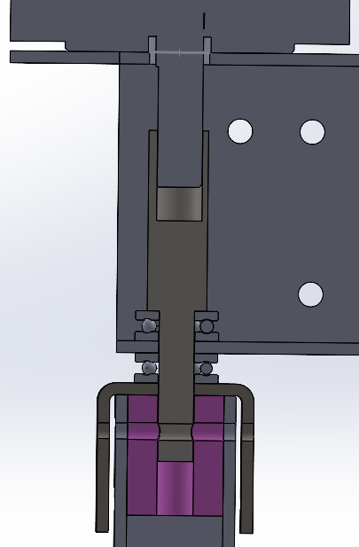
- Stepper Motor: Directly drives the steering shaft without intermediate reduction gears. This eliminates backlash, reduces total part count, and removes gear-tooth wear as a potential failure point.

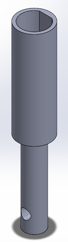
- Custom Interface Shaft: Machined shaft tapped at the side and secured to the stepper motor shaft via a set screw. It translates the rotational output of the motor shaft into a rigid mechanical connection for the turning core. It was designed in such a way that for some reason the interface shaft was pushed upwards it would not load the axial direction of the stepper motor shaft. (Note: In this image the set screw is not present as that was an addition made during manufaturing as the creation of D-bore with the chosen material was deemed not possible with the equiment at Cube.)
- Lower Core Block (Plastic Cube): Connected securely to the upper interface shaft it aids in a more even tranfer of torque form the shaft to the vertial square tubes, provides support for the screws connecting the U-shaped bracket to the vertical square tubes and interface shaft, and supports the U-shaped bracket in the center where the thrust bearing load is.
- Vertical Square Tubes: Act as the primary load-bearing rotating columns for both the front and rear steering assemblies. The vertial load is carried upwards with this tube and then trasnferred to the U-Bracket, which transfers it to the thrust bearings which then trasnfers it to the suspension system.
- U-Shaped Steel Brackets: Mounted to the exterior of the vertical square tubes. They provide a flat, rigid metal surface that prevents localized plastic crushing under heavy structural loads.
- Thrust Bearings: Positioned flush against the steel brackets. They isolate the vertical forces caused by the weight of the rover enabling smooth rotational motion under full payload.
Design Rationale
Version 1: The initial concept attempted to use a 3D-printed gear (30 mm diameter) driven by an M6 60 mm bolt and hex nuts pressed into embedded cutouts inside the plastic cube. This was was the first idea that came to mind when thinkning of not exceeding the axial load limit of the stepper motor.
- Primary Failure Mode 1 (Gear Shear): The main probelm foreseen with this concpet was that under high torque the gear could bend causing jumping/slipping whihc would not be ideal. Another probelm was the gear would degrade quite quickly.
- Primary Failure Mode 2 (Interface Stripping): High torque from the stepper motor concentrated immense torsional forces onto the sharp corners of the embedded hex nuts. Because plastic yields easily under point loads, the nuts quickly stripped out their plastic pockets, causing total loss of rotational control.
- Primary Failure Mode 3 (Nut loosening): Since the system relies on two nuts that are screwed into each other to create a lock; under high amounts of torque and continuous vibration, these nuts would eventually loosen making the turning system useless.
Version 2 (Current Production Design):
- Direct Drive Integration: Eliminating the printed gears entirely removed the primary shear risk. Driving the turning column directly ensures 100% torque transmission from the stepper motor without intermediate mechanical loss.
- Metal-on-Metal Fastening: Switching to a tapped metal interface block with set screws distributes clamping pressure evenly across the flat of the motor shaft. This prevents the rounding and stripping experienced in plastic cutouts.
- Axial Load Isolation via Thrust Bearings: Standard radial bearings or plain plastic bushings degrade quickly when subjected to heavy vertical loads down the steering axis. Placing thrust bearings against rigid U-shaped steel brackets creates a dedicated path for vertical forces to pass through the frame. This protects the internal stepper motor bearings from dynamic impacts during travel and maintains low rotational friction.
Failure Modes and Future Work
The turning system is one of the more intrecate parts of the drive system, but in this case it was one of the more rushed systems as time was running out and the main focus was getting a subsystem that worked for now and could be improved on in the future.
- U-Shaped Bracket Tolerancing: Since the U-shaped bracket relies on bending to create it, it sufferes from multiple steps that are quite inaccurate. One must first score the original plate, then line up the scored line by eye in the bending machine, and then bend the plate. This must be done for both sides as the machine can only do one side at a time. This process is very inaccurate and causes that the holes do not line up well, the dimensions to be off, etc. This is why in the current rover they do not exist. They were replaced with washers. This combined with other oversights caused quite some problems with the lower part of the suspension system.
- Improvement: Either find a way to produce these brackets with more accuracy or find extruced channels that achieve the same goal. Ideally a system that is much improved from this would be prefered.
- Interface Shaft Under Constrained: Currently the interface shaft only has one hole that connects the stepper motor to the vertical tube. This means that at it only connects the lower part of the suspension system to the upper part through this hole. This has 2 probelms. The first being the reliance on one sigular M3 screw that holds the turning and therefore that part of the suspension system together. The other being that it does not contrain all the degrees of freedom, as in if the vertical tube was not pressup against the main suspension part it would be able to wiggle and rotate around that point. While the singular M3 screw is fine (it only needs to carry a load if that specifc wheel is in the air), it could pose a probelm if an irreguar force acted on it which could break it.
- Improvement: Create interface shafts that are longer as to include more through holes in order to increase the amount of screws.
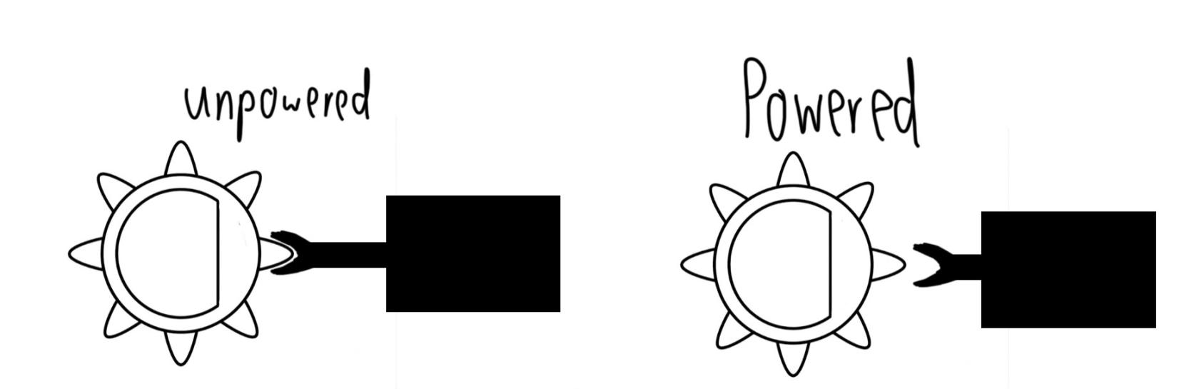
- No Rigid Hold when Unpowered: According to the rules of the ERC the rover needs an emergency shutoff button. Currently the wheels can only hold their currect angle while powered. In the event that the button needs to be pressed, the stepper motor becomes unpowered and the wheels will then proceed to turn in thier own, unpredictable way. This can cause a probelm in the case the wheel sharply turns perpendicular to the motion of the rover, potentially causing damage to the suspension system as there is quite a lot of momentum when needing to quickly stop.
- Improvement: Add a physical stop that is only activated when the unpowered. First rough idea would be including a gear like structure mounted on the stepper motor or interface shaft with a solanoid with a negative gear like piece attached to the end that is extended when inpowered and retracted when powered. An example is given below. This could be hidden away in the horizonal memebrs of the suspension system.

- Improvement: Add a physical stop that is only activated when the unpowered. First rough idea would be including a gear like structure mounted on the stepper motor or interface shaft with a solanoid with a negative gear like piece attached to the end that is extended when inpowered and retracted when powered. An example is given below. This could be hidden away in the horizonal memebrs of the suspension system.
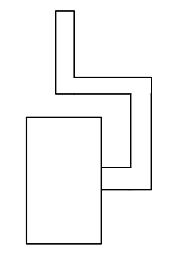
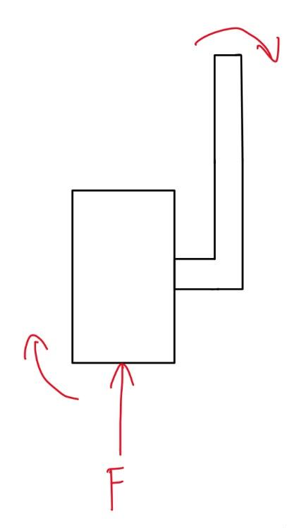
- "L" Shaped Turning System Causes Unwated Moment: With the way the motor subassembly is currently mounted the entire turning system creates an "L" shaped system. The leftmost picture picture describes how this moment is created when the systme is loaded. This comined with the problems seen in the first two failure modes compounds the unwated camber of the vertial part of the suspension system. The reason this was done was that when faced with the "making everything modular" probelm, another system such as a "U" shaped system seen on actual mars rovers was seen to be more complex to figure out. In hindsight this could have been solved quite simply, such as creating 90° brackets similar to the ones used for the main members of the suspension system.
- Improvement: For the reveal event, a rudementary "U" shaped system was fashioned. This is not a complete system as there is no connection to the stepper motor responsible for the turning. an example can be seen on the rightmost image.
Motor Subassembly
The drivetrain report details the original V1 concept (left). However, just 2–3 weeks before the qualification video deadline, the decision to change motor suppliers and therefore motors was made. V2 (right) is an adaptation designed to integrate alternative motors on short notice while repurposing as many V1 hardware interfaces, adapter plates, and mounting geometries as possible. This ended up making the mouting interface between the motor and the hub quite a bit easier. The older motor had a long planeteray gearbox attached to it, which required a "cage" around the motor-gearbox combination to protect it from the spinning wheel surrounding it. This coupled with a singular point of attachemnt for the wheel requireing pre-loading on the pilot screw to prevent the screw from becoming undone during operation increased its complexity. The new motor is larger is an all in one motor/gearbox solution with 6 M3 mounting points. this made it drastically easier to mount.

1. Motor Requirements and Motor Choice
The main equations governing the torque requirements are the ones listed below. For the first time the absolute worst case scenario was chosen as no one knew the exact challenges the rover would face in the terrain department.
- Rolling Resistance: m · 9.81 · Crr · cos(θ)
- Gravity Component: m · 9.81 · sin(θ)
- Total force: Rolling Resistance + Gravity Component
Units | Value |
Rolling Resistance (Crr) | 0.5 |
Mass (kg) | 75 |
Inclination Angle (°) | 60 |
Pulling the rover up an angle of 60° sets the required force of 821N. That is why the wheel size was set to 200mm. Set the required torque to 82.1 Nm across all wheel. Since the idea of a 4 wheeled rover was always a topic of debate due to its superior maneuverability comapred to 6 wheeled rovers, the torque per wheel was calculated for 4 wheels. This was done so that the upfront investment in drive motors today would be high, however, in the long run it would be cheaper than buying 6 less powerful motors now and then 4 more powerful and more expensive motors later. This also has the added benefit that in the case that a 4 wheeled rover is made, there are more spares. The maximum speed of the rover is set at 1 m/s this means that the motor should spin at 95.5 rpm with the current wheel size.
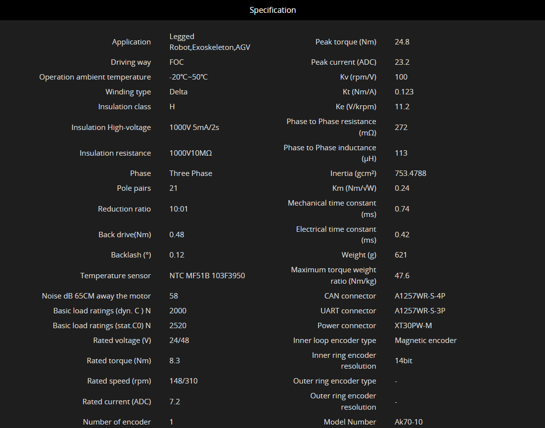
For V1 the EC 60 flat Ø60 mm, brushless, 200 W motor and Planetary Gearhead GP 52 C Ø52 mm, 4 - 30 Nm, Ceramic Version gearbox combination by maxon motors was chosen. But since this did not work out, for V2 the AK70-10 KV100 by CubeMars was selected. This motor was not only cheaper, but supported a higher torque and higher motor output speed all while being coming in a more compact package and facilitating both 24V and 48V compatiability. This was very useful as a 24V architecture was decided on at the beginning of the year, however this motor could allow for a more efficiet 48V architecture in the future. More of its specifications are listed below.
2. Subassembly Overview
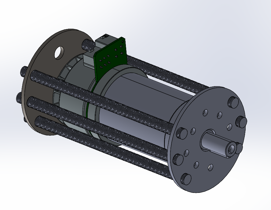
- Primary Role: Provide a mounting point for the motor while also also protecting it from the spinning wheel surrounding it.
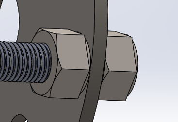
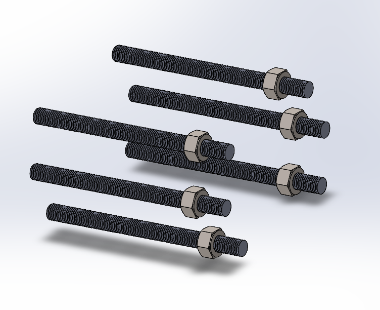
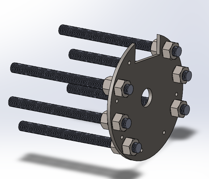
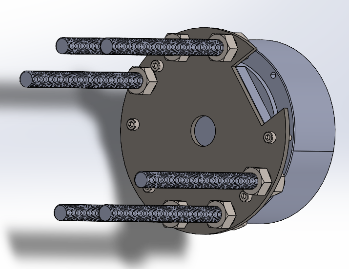
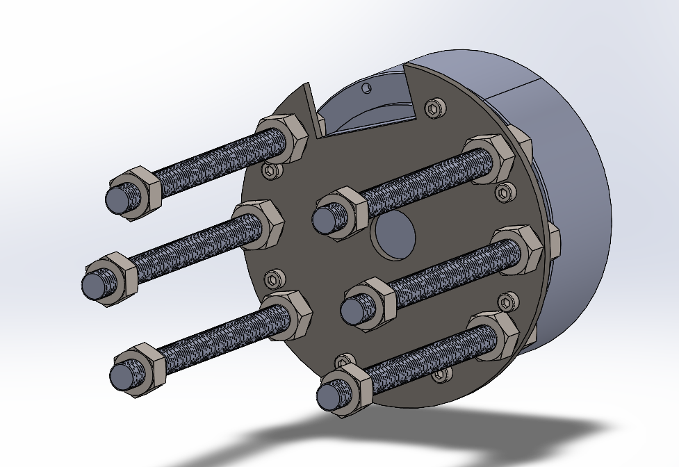
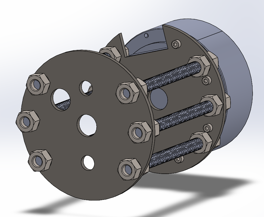
- Design Philosophy: Since the goal at the beginning of the year was to have every component be modular and easily replaceable it was quite tricky to come up with a nice solution. Therefore, six M8 threaded rods were chosen each cut at 140mm (currently cut to 110mm for the new motor). This was done as according to rough FEM simulations, when loaded, these six rods would only bend about 1-2mm. Keeping this displacement low meant that "squatting"or unwanted camber is mitigated. The plates, where the motor is mounted and where the subassembly is mounted to the suspension, are held inplace with nuts that are tightened into each other clamping the plate between them. While this is not the best solution, it works well enough that till this point a motor subassembly has not fallen apart during operation.
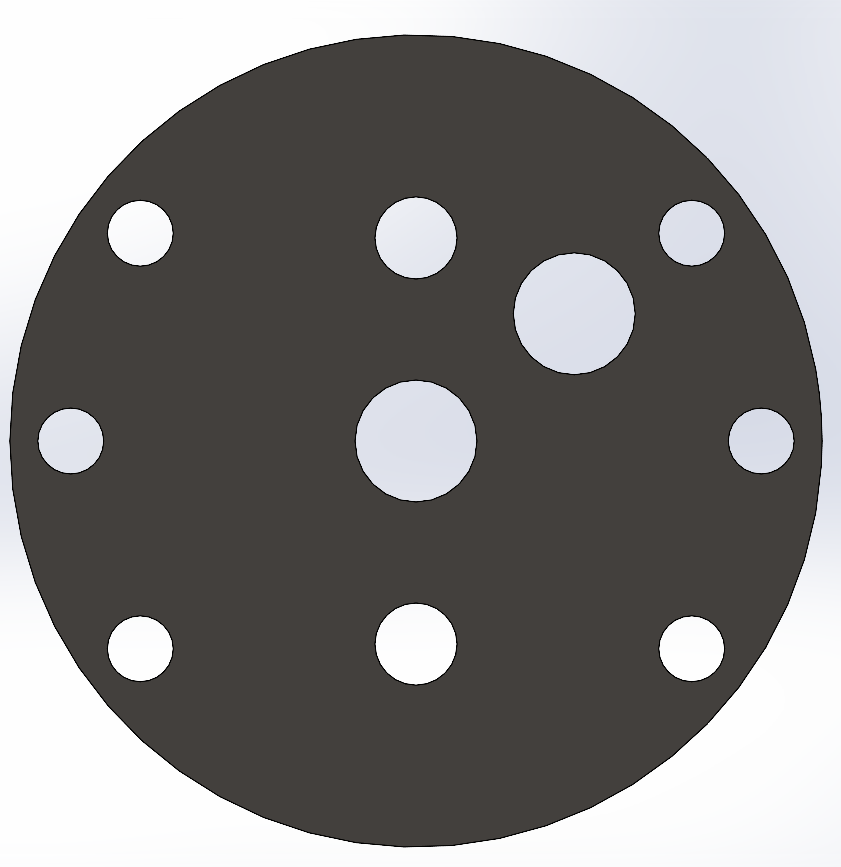
The subassembly is attached to the suspension system using two M10 bolts. The hole in the center was just a copying error from the motor mounting plate from the first version. The big hole positioned off to the right is meant for cable management. While it works at the moment, it is a bit too small. In the future, enlarging the hole in the middle and then cutting another hole in the vertial arm of the suspension system to allow cables through. This was not possible for V2 as that entire section of the motor subassembly and suspension system was designed for the V1 motor.
3. Assembly & Alignment Guide
Assembly Procedure:
Step 1:
| Step 2: Slide M8 rods into the holes cutout of the motor mouting plate, then screw in the other nuts that clamp the plate in place.
|
Step 3: Attach motor
| Step 4: Screw in inner nuts for the plate that mounts the motor subassmbly to the rest of the suspension system.
|
Step 5: Attach plate and clamp with the remaining nuts.
|
4. Known Limitations & V3 Recommendations
- Ingress Protection (Dust & Debris): The open threaded-rod structure leaves the motor and wiring completely exposed to dirt, sand, and moisture.
- Alignment Issues: Since the nuts are all hand screwed in and there is no stop, alignment has to be done by eye which can result in misaligned plates.
- Vibration Loosening: It has been noted that increased vibrations (tapping againt the table, vibration during driving etc.) can cause the nuts to loosen if they werent tightened enough.
- Recommended V3 Upgrades:
- More Robust Mounting: With the new motor, many more mounitng options become avaliable. This means that the threaded rods can be removed. For a first run they were a good proof of concept, but they have their issues. A precise mounting solution for the plates is required.
- Enclosed Housing: Currently the motor sits within the wheel hub so it is relativly protected from the elemets, however, dust, dirt and water can still get in. Covering the motor and its cables is quite important as these contaminants can damage these components.
Wheels and Wheel Hubs
Overview & Design Intent
The rover uses a non-pneumatic, cellular wheel design. The goal of this was to provide compliant deflection, passive damping, and terrain conformity without the risk of punctures or pressure loss. While technically these wheels would not be feasable on the martian surface due to temperature fluctuations and radiation, these wheels will be fine since the competition takes place on earth.
The deep dive into the engineering, geometry, and finite element method (FEM) optimization lives in the companion report: "Design and Development of a Rover Drivetrain". Check that document if you need to understand the structural load calculations or deformation simulations.
Requirements
- Primary Role: Provide ground traction, terrain conformity, and passive shock absorption for the drivetrain.
- Target Load: 12.5kg per wheel
- Outer Diameter / Width: The diameter of 200mm was chosen due to the torque requirements in the worst case scenario being to high. The width was chosen to be 140mm because the original motor and gearbox combination that was supposed to be used with these wheels was that length.
Material Choices
- Outer Tire (TPU 95A): TPU 95A was chosen as it was flexible enough so that it woud not get damaged with hard impacts but also not too flexible like TPU90A which would have required more material for similar rigidity. This would have made the wheel heavier, increased its printing time, and increased its cost.
- Inner Hub: Currently the hubs consits of 3 differnet materials, PA6-CF20, Fiberon PETG rCF-08 and Polymax Polycarbonate. The first 2 were printed from PETG rCF-08 as that was the strongest filament on hand at that time. These were done at 100% infill, however this caused a problem known as the "blob of death". This is when the print nozzle slighlty collides with already printed lines, causing a buildup of matieral which if not stopped can cause the material to buildup all the way into the printhead wiring and if not carefully removed can cuase damage to the wiring which is a big annoyance to fix. So for the following hubs an infill of 80% was decided as that was the infill where no blob was seen.
The next 2 were printed from polycarbonate as the general idea was that these were stronger than the PETG rCF. While this is true in general, the specific verion of ploycarbonate (Polymax) from polymaker is generally weaker than other polycarbonates (Polylite) and even the PETG rCF. While it seems to have held up to this point, extensive stress tests have not been conducted in order to see their long term feasibility.
The final 2 where made from PA6-CF20. It is one of the strongest filaments offered by polymaker. It is very rigid and the best filament for this purpose as the entire rover's weight rests on the mounting points that connect the hubs to the plate that connects to the motor. In the future this should be used mainly for the hubs if the same design is kept, however other materials could suffice such as CoPA, Polylite PC, or others depending on the weight of the rover.
Manufacturing & Assembly Guide
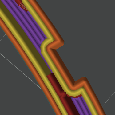
All prints used OrcaSlicer's calssic wall generator (left) instead of Arachne (right). While Arachne is quicker is does this by having variable wall thicknesses. This can cause rounded corners to form when a sharp corner is needed which can affect tolerance accuracy.

1. 3D Printing Settings
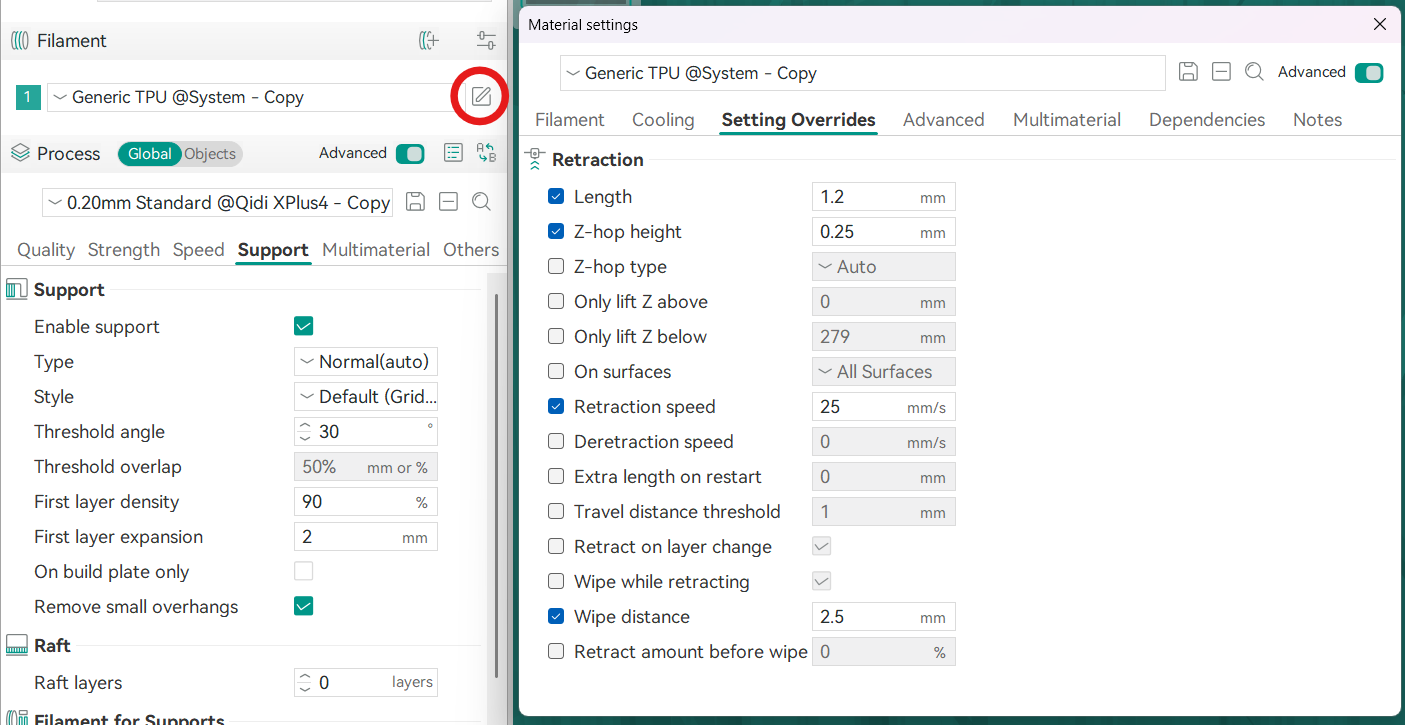
- TPU 95A Tire Settings: Due to TPU's flexibility printing with it can be quite a pain, however, OrcaSlicer's Generic TPU present is quite good. A few tweaks were made to the material settings in OrcaSlicer in order to mitigate the stringing which can cause the wheel to not only look ugly, but can affect tolerances. These settings can be tweaked further, but at the moment these seemed to balance stringing mitgation while not underextruding too much. The main changes were done to the retraction settings seen in the image below. An increase in the retraction length prevented material from oozing out the nozzle when we do not want it to. Retraction speed was put to 25mm/s as too quick of a retraction can cause the TPU to bend and tangle inside the extruder. Wipe distance is how far the nozzle will go back over the section it just printed before moving to the next section. This is to remove any material that oozed out the nozzle post retraction. Increasing this can reduce stringing, but can also increase printing time. Z-hop hieght was set to 0.25 as the layer height was set at 0.2 so the defualt of 0.4 was too high and increased printing time.

- PA6-CF20 Hub Settings: The present in OrcaSlicer is good for this. Has to be printed in the QiDi or similar that has an enclosed printing bed as this material likes to absorb moisture. Another requirement is that the printer needs to have a hardened nozzle as this material contains carbon fiber which is very abrasive (already installed as standard on the QiDi just make sure other printers obtained in the future has this as well). The material should also be kept in an enclosed box while printing as again, it absorbs moisture very easily.
2. Component Interfaces
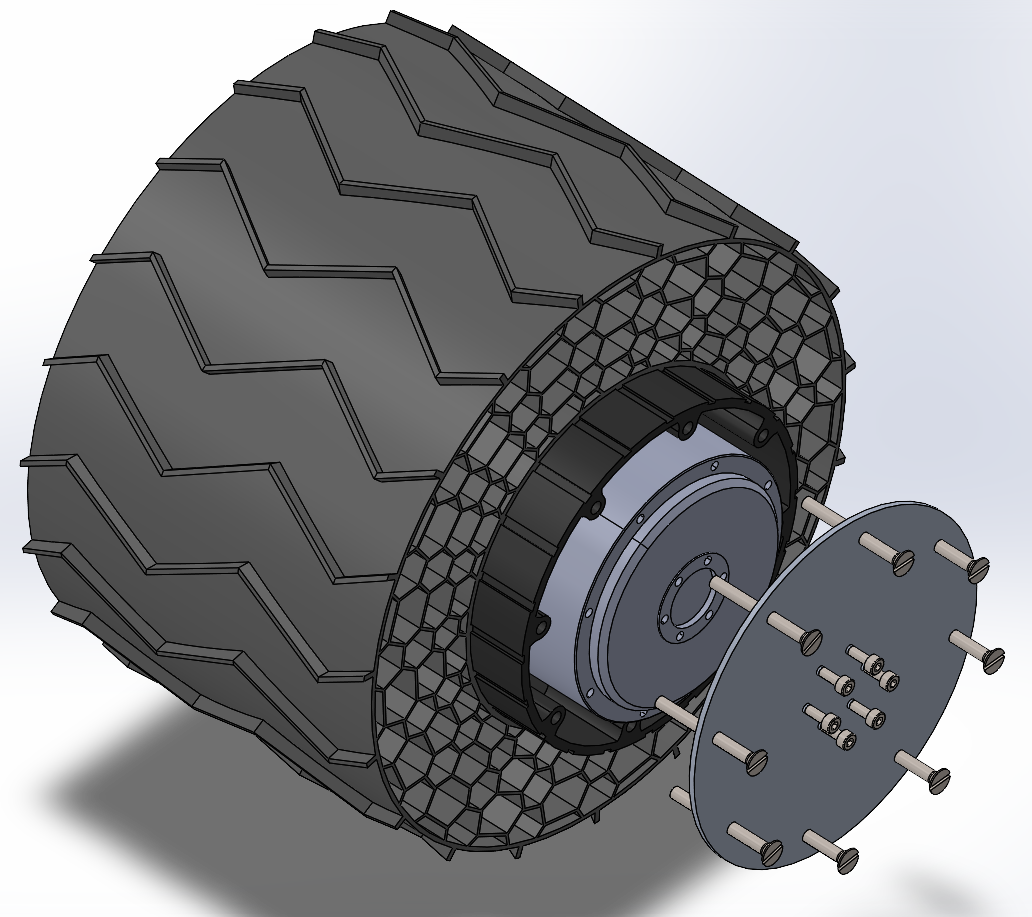
- Tire-to-Hub Interface: The tire to hub interface relies on a spline connection and a press fit. This was done by first creating the hub then using the cavity feature in SOLIDWORKS to cut the negative from the wheel. From there a face offset of 0.1mm was added for some tolerance as when 3D printing, the parts tend to contract and expand.
- Hub-to-Gearbox Interface: Connecting the hub to the motor is an aluminum plate denoted by DS25264003 V2. 8 M4x40 screws screw into nuts that are postioned behind the hub mouting points. 6 M3x8 screws screw into the motor.
3. Maintenance & Lessons Learned
The wheels have not been properly stress tested so no proper wear indicators have been determined. One problem that did however become aparant is the mounting between the hub and the tire. While most mounts seems to be fine, on a specifc hot day when the wheel and polycarbonate hub was exposed to 40°C+ surface temperatures, the wheel started to slip off the hub. The main theory behind this is that when the wheel was exposed to this temperature, it expanded and since the polycarbonate is smoother than the other hubs , it started to slip off. A quick fix would be to glue these hubs to the wheels but if the wheel or hub becomes damaged, both parts would need to be replaced. A better system could be created when combined with a motor subassembly redesign.