Communication system
- Ethernet Driver
- Setup of Embedded Ethernet
- Sending your first message
- Ethernet Testing
- Extra Functions
- Debugging
- Issues
- Protobuffers
Ethernet Driver
The documentation for the embedded Ethernet driver
Setup of Embedded Ethernet
This page: How to set up ethernet.
Introduction
Ethernet is the protocol used to communicate between all the components. It uses the auto-generated Ethernet driver code from cubeMX to use the physical Ethernet peripheral. It also uses LWIP to do the lowest levels of packet handling. Lastly, we use freeRTOS for multi threading. The current implementation cannot work without it.
CubeMX
CubeMX is used to automatically generate setup code for the stm32. To use Ethernet you have to set up a few things in cubeMX.
To write this driver I mostly used videos from ControllersTech on YouTube. The most useful video is STM32 Ethernet (Part 1): How to configure Ethernet peripheral and perform successful ping test [1]. So if you do not understand anything, watch that video.
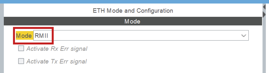
1) ETH
ETH is under connectivity in cubeMX. It sets up the Ethernet peripheral. Set it to RMII mode.
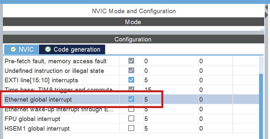
NVIC > NVIC
Turn on Ethernet global interrupt in NVIC settings.
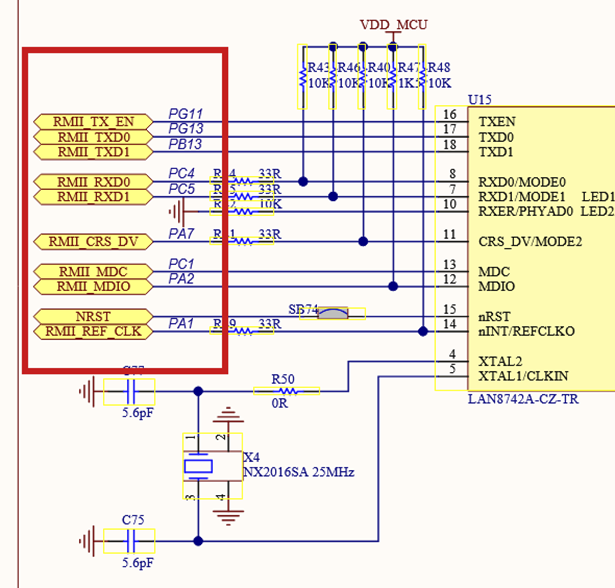
ETH > GPIO settings
When Ethernet is enabled, the pins should automatically be configured according to the below schematic. This can be wrong, please confirm it!
Setup all the PINS like it is done in the PIN schematic (Download: MB1364-H753ZI-C01 Board schematic, pg. 6) [2].
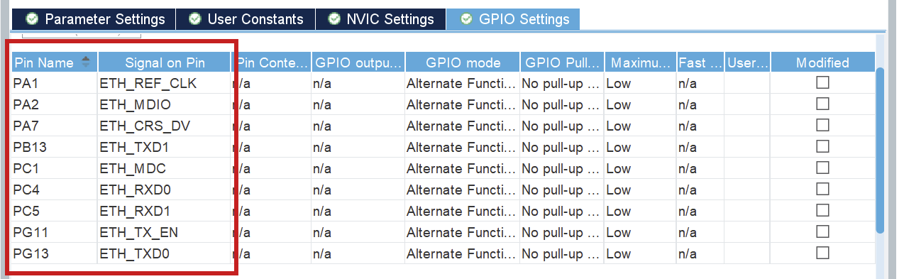
Troubleshooting: Pins not set as schematic
If any of the pins are not as in the schematic, refer to the above information. You can click each pin in CubeMX and choose the correct function (e.g. ETH_RXD0), the other (incorrect) pin will be automatically disabled.
2) LWIP
LWIP is a middleware generated by cubeMX. You can find it under middleware.
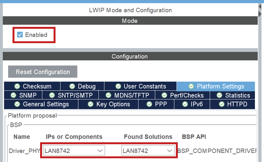
LWIP > Platform Settings
Set up LAN8742, to signal that that is the physical Ethernet driver you use.
LWIP > General settings
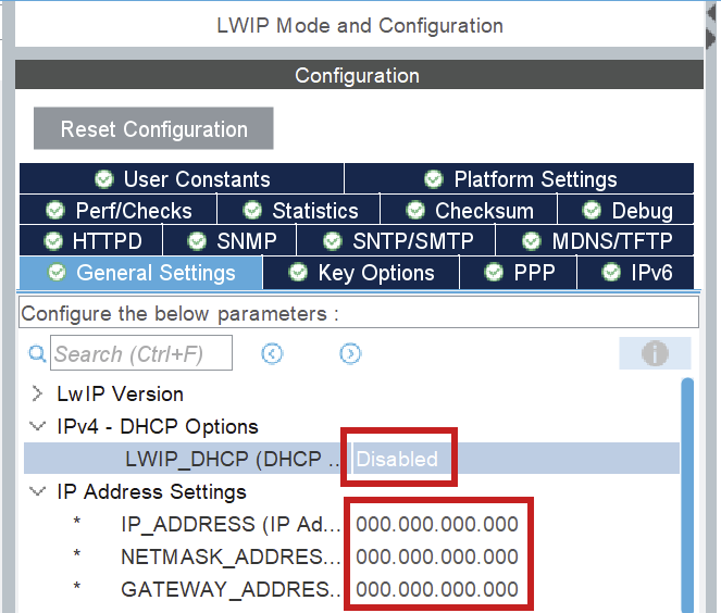
The most important configurations here are the DHCP (DHCP = Disabled) and IP address settings.
The IP address settings don't matter, they will be overwritten in a configuration file in the code.
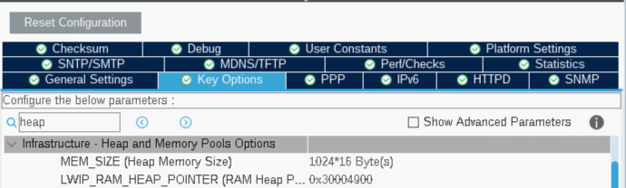
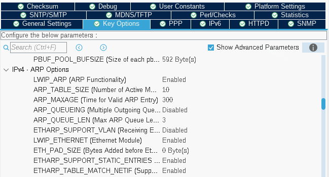
LWIP > Key options
The most important part of the tab Key options is to check if LWIP_ARP = Enabled. You also need to keep track of the MEM_SIZE (Heap Memory Size). Start with a value of 1024*16 bytes. LWIP_RAM_HEAP_POINTER should be 0x30004900 such that the heap doesn't overlap different memory. That is the value I use, but it can be changed if need be.
Lastly, you need to add ETHARP_SUPPORT_STATIC_ENTRIES = Enabled. This is only shown when you turn on Show Advanced Parameters.
3) CORTEX_M7
You can find CORTEX_M7 under System Core.
CORTEX_M7 > Parameter Settings
Turn on CPU ICache and CPU DCache.
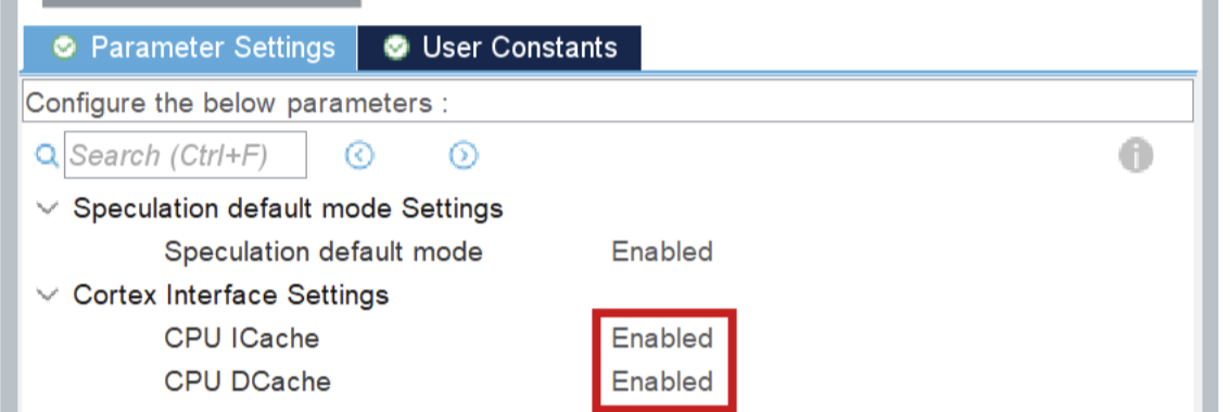
Setup memory protection like seen below:
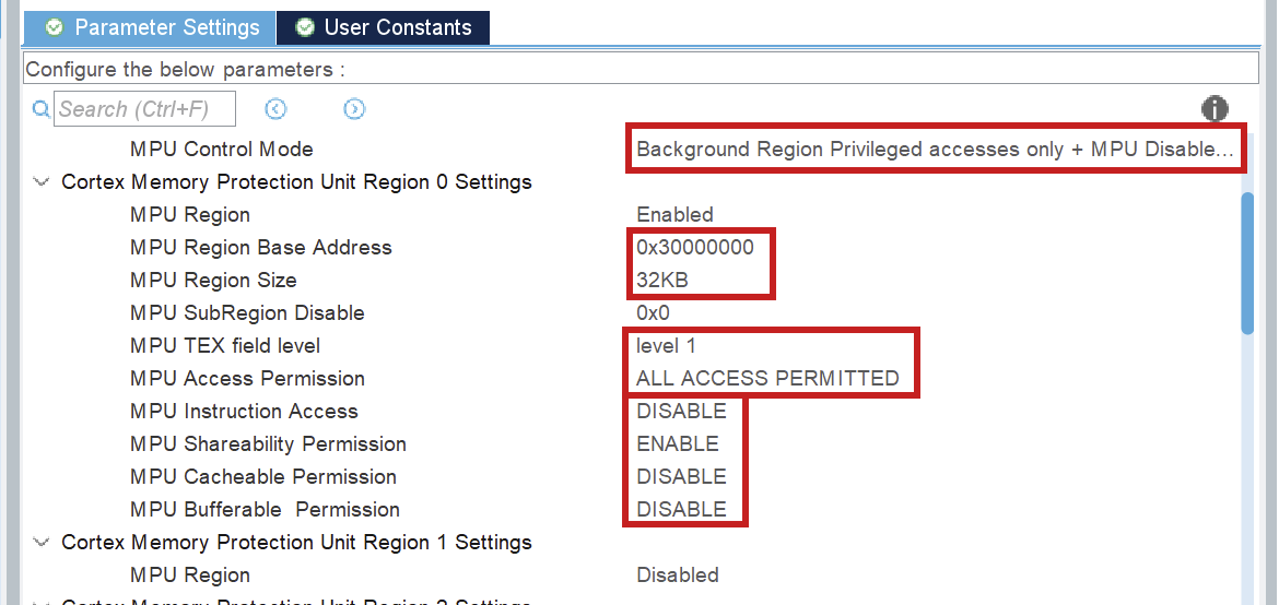
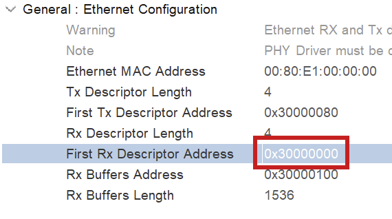
The MPU Region Base Address is the address of the first Rx descriptor (ETH > Parameter Settings > General). The MPU region size is calculated using heap memory size and the RX buffers. Watch the video [1] mentioned above for more information.
4) FreeRTOS
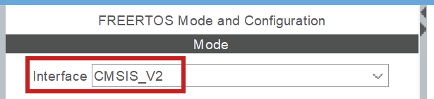
Freertos is automatically integrated in LWIP if you turn it on in cubeMX. It does not have to be modified, it just has to be turned on. Make sure you use CMSIS_V2, because V1 did not work well.
NOTE: when you use FreeRTOS, you will have to select another SYS Timebase Source. Go to SYS > Timebase Source and select any of the free timers, just make sure it is NOT SysTick. Make sure you do not use that timer for any other activities.
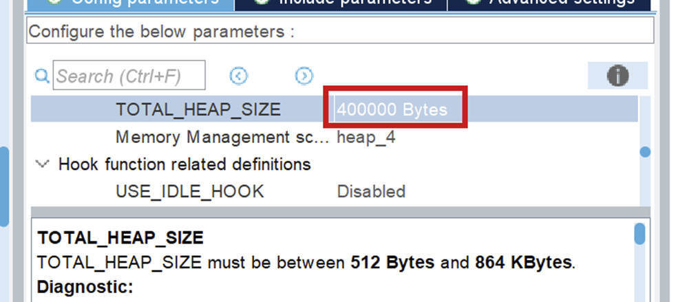
Make sure you set your TOTAL_HEAP_SIZE to a sufficient number. When it is not big enough, the threads that you will create using FreeRTOS will suffocate and not work. This will also not give you any errors so watch out for it!
The Code
After you generate the code for your board, you can look through networking component, in the ethernet.h file, to see all public Ethernet functions.
For a full guide of how to use Ethernet, I refer you to Driver usage [3].
Resources
- STM32 Ethernet (Part 1): How to configure Ethernet peripheral and perform successful ping test
- PIN schematic (Download: MB1364-H753ZI-C01 Board schematic, pg. 6)
- Driver usage
Sending your first message
This page: how to initialize your Ethernet driver and send your first message. A lot of constants can be seen in the explanatory code. Those can be found in components/common/networking_constants. They are also added at the end of this file.
The functions that are used for Ethernet can be found in components/common/networking/inc/ethernet.h.
The headers in the folder components/common/networking/stm/ are only to be used inside the Ethernet driver!
NOTE: The implementation only works with FreeRTOS, but it works fine with only 1 thread. Before you implement anything, do an introductory tutorial on FreeRTOS!
Code Usage
1) Linker file updating
In the linker file, you need to say what memory addresses LWIP uses. You set these values in Cubemx and the sections are generated for you, but you have to add it to the linker file yourself.
You can find your linker (.ld) file in components/{env_name}/firmware/
The codeblock added for the default values is:
.lwip_sec (NOLOAD) :
  {
      . = ABSOLUTE(0x30000000);
      *(.RxDecripSection)

      . = ABSOLUTE(0x30000080);
      *(.TxDecripSection)

      . = ABSOLUTE(0x30000100);
      *(.Rx_PoolSection)

  } >RAM_D2
You can just use the generated linker file and append to it, because it never gets regenerated, but you can also create a new one. If you create a new one, you have to put in the platformio configuration file that you use the new linker file. An example of how to do it is shown below. The path is relative to where the platformio configuration file is located.
board_build.ldscript = components/network_board/firmware/STM32H753XX_FLASH.ld2) Code initialization
When you first use the Ethernet driver, you have to initialize a few things.
First make sure that HAL is initialized, the D and I cache are enabled, the system clock and the memory protection unit as well. These auto-generated functions start processes that Ethernet uses.
//Initialize HAL
HAL_Init();

//Enable D&I cache (for ETH)
SCB_EnableICache();
SCB_EnableDCache();

//Start the system clock
SystemClock_config();

//Memory protection unit
MPU_Config_wrapper();
Note for debugging with SCB_EnableDCache()
When debugging and trying to step over SCB_EnableDCache(), the program will keep infinitely running unless you place a breakpoint on the next line while in active debugging mode.
ETH_Init(...)
result_t ETH_init(linkstatus_callback_t link_state_change_callback,
                  uint8_t ip[4], uint8_t netmask[4],
                  uint8_t gateway[4],
                  uint8_t mac_address[6])
For ETH_init, the link_status_change_callback can be set to NULL, to use the default function. The others have to be set. For initial testing you can set these to the same values as set in CubeMX.
Example usage of ETH_init(...)
//Example values
uint8_t ip[4] = {192, 168, 0, 223};
uint8_t mac[6] = {255, 255, 255, 255, 255, 255};
uint8_t gateway[4] = {192, 168, 0, 1};
uint8_t netmask[4] = {255, 255, 255, 0};

ETH_init(NULL, ip, netmask, gateway, mac);
NOTE on multithreading: make sure you set the stack size big enough (I use .stack_size = 1024 * 8) when setting the task_attributes for the thread Ethernet will be running in!
ETH_udp_init()
void ETH_udp_init(uint8_t sender_prio_buf,
                  QueueHandle_t *send_queues,
                  receive_callback_t receiver_callback)
sender_prio_buf
Defines the number of priority queues you use for queuing the send messages. The queues we use are freeRTOS queues. More information can be found here.send_queues
You need to pass freeRTOS queues as a pointer to an array. The queues need to be implemented before passing them toETH_udp_init(...), see below.
Example queue implementation
int SendQueueSize = 80;

//Create queue 1
static StaticQueue_t xStaticQueue1;
uint8_t ucQueueStorageArea1[SendQueueSize * ETHERNET_SQ_ITEM_SIZE]; //NOTE: constants from <ethernet_constants.h>
QueueHandle_t udp_receiver_queue1 = xQueueCreateStatic(SendQueueSize, ETHERNET_SQ_ITEM_SIZE, ucQueueStorageArea1, &xStaticQueue1);

//Create queue 2
static StaticQueue_t xStaticQueue2;
uint8_t ucQueueStorageArea2[SendQueueSize * ETHERNET_SQ_ITEM_SIZE];
QueueHandle_t udp_receiver_queue2 = xQueueCreateStatic(SendQueueSize, ETHERNET_SQ_ITEM_SIZE, ucQueueStorageArea2, &xStaticQueue2);

//queues object we pass as an argument later
QueueHandle_t queues[2] = {udp_receiver_queue1, udp_receiver_queue2};
receiver_callback
This can be any function that takes areceive_frame_t, found inethernet_udp.h. However, we also implemented a "packet dispatcher", to handle incoming packets.
More information about the packet dispatcher is in the Packet Dispatcher documentation.
Example implementation WITHOUT packet dispatcher
void HandlePacket(receive_frame_t *receive_frame) {
 printf("Wayoo, message received");
}

int main(void) {
  ...
  /*The other code examples above would go HERE */
  ETH_udp_init(2, queues, HandlePacket);
  ...
}
Now Ethernet is started and you can receive packages!
3) Sending Packets
ETH_add_arp(...)
result_t ETH_add_arp(uint8_t ip[4], uint8_t mac[6], int retry_count)To send to a certain IP, you have to set the ARP table. Otherwise, it will only send ARP resolution messages. You do that by using the ETH_add_arp(...) function with the IP you want to send to, and any random mac address.
WARNING: Make sure you have initialized udp before using ETH_add_arp(...)!
ETH_udp_send(...)
void ETH_udp_send(uint8_t ip[4],
                  uint8_t port,
                  uint8_t *payload,
                  uint16_t payload_len,
                  uint8_t prio_num)
payload
The payload can be any byte array, where the size of that byte array is the 4th argument:payload_len.prio_num
Priority level for transmission. Must be less thansender_prio_bufspecified inETH_udp_init(...).
Now you can send messages!
Example: sending a message
//NOTE: These are the receiving ip/mac,
//not the sending ones we specified earlier
uint8_t ip[4] = SAMPLE_BOARD_IP;
uint8_t mac[6] = SAMPLE_BOARD_MAC; //constants from <ip_mac_constants.h>

ETH_add_arp(ip, mac, 5);

uint8_t packet1_payload[4] = {14,06,20,04};
ETH_udp_send(ip, 8, packet1_payload, 4, 1); //Send a single packet
Appendix
1) Networking_constants
#ifndef IP_MAC_CONSTANTS
#define IP_MAC_CONSTANTS

#define SAMPLE_BOARD_IP {192, 168, 0, 111}
#define SAMPEL_BOARD_MAC {0x00, 0x80, 0xe1, 0x00, 0x00, 0x00}

#define NETWORK_IP {192, 168, 0, 223}
#define NETWORK_MAC {0x00, 0x43, 0x23, 0xee, 0x21, 0x64}

#define GATEWAY {192, 168, 0, 1}
#define NETMASK {255, 255, 255, 0}
#endif //! IP_MAC_CONSTANTS
2) Full Example Code
Import "networking_constants.h" and "ip_mac_constants.h" to use the predefined test constants
#include "ethernet.h"
#include "networking_constants.h"
#include "ip_mac_constants.h"


/* Callback function that handles a specific packet*/
void HandlePacket(receive_frame_t *receive_frame) {
    printf("Wayoo, message received");
}

int outgoing_counter = 0;
int main(void) {
    /*Inits*/
    HAL_Init();
    SystemClock_Config();

    MPU_Config_wrapper();

    SCB_EnableICache();
    SCB_EnableDCache();

    MX_GPIO_Init();

    /*Config + init sending side*/
    uint8_t mac[6] = NETWORK_MAC;
    uint8_t ip[4] = NETWORK_IP;
    uint8_t netmask[4] = NETMASK;
    uint8_t gateway[4] = GATEWAY;

    ETH_init(NULL, ip, netmask, gateway, mac);

    /*Making queues*/
    int SendQueueSize = 80;

    static StaticQueue_t xStaticQueue1;
    uint8_t ucQueueStorageArea1[SendQueueSize * ETHERNET_SQ_ITEM_SIZE];
    QueueHandle_t udp_receiver_queue1 = xQueueCreateStatic(SendQueueSize, ETHERNET_SQ_ITEM_SIZE, ucQueueStorageArea1, &xStaticQueue1);

    static StaticQueue_t xStaticQueue2;
    uint8_t ucQueueStorageArea2[SendQueueSize * ETHERNET_SQ_ITEM_SIZE];
    QueueHandle_t udp_receiver_queue2 = xQueueCreateStatic(SendQueueSize, ETHERNET_SQ_ITEM_SIZE, ucQueueStorageArea2, &xStaticQueue2);

    QueueHandle_t queues[2] = {udp_receiver_queue1, udp_receiver_queue2};

    ETH_udp_init(2, queues, HandlePacket);

    /*Config + add ARP receiving side*/
    uint8_t ip[4] = SAMPLE_BOARD_IP;
    uint8_t mac[6] = SAMPLE_BOARD_MAC;

    ETH_add_arp(ip, mac, 5);

    /*Sending a message*/
    uint8_t packet1_payload[4] = {14,06,20,04};

    /*Test sending*/
    while (outgoing_counter < 100) { //NOTE: after 80 packages the queue will be full!
          ETH_udp_send(ip, 8, packet1_payload, 4, 1);
          osDelay(10);
          outgoing_counter += 1;
          LOGI(TAG, "%d", outgoing_counter);
      }

}
Ethernet Testing
Send Testing
Requirements
- STM32
- Ethernet Cable
- Wireshark
Testing
Send testing is easy. The only thing you have to do is upload the setup and sending code to your STM32 and connect it to your PC/laptop using an Ethernet cable. Then you can go into Wireshark, look at the activity on you ethernet periphial, to see if it sends something. It also logs to the terminal if you send, if you have turned logging on.
Receive Testing
Requirements
- Linux laptop 🫠
- STM32
- Ethernet Cable
Connect the Ethernet cable between the STM and the laptop that is sending you packets. - Any pcap packet sender
We recommend packeth, installation manual will be below. - Wireshark (optional)
Installation of Packeth
NOTE: you need a Linux laptop for this
Testing
Receive testing is done by sending packets, saved in test/networking, to the STM32 using a pcap packet sender. If you want to use new packets, I advise to send the packet you want from the STM32. Then use wireshark to save the packet such that you can send it back. In wireshark you can see, when you send a package, to which IP and MAC it is being send, and it should match with your IP and MAC.
To see if the messages are received, make sure you print messages in your receive function. Then check the serial
Extra Functions
Introduction
This documentation is about extra functions, that are not necessary to get it running, but can be used if need be.
Non-deprecated functions
ETH_setup_MAC_address_filtering
This function is used for perfect mac address filtering. It is used by giving it MAC-addresses as arguments. If you receive packets with those addresses, they will also be processed.
Deprecated Functions
There are deprecated functions for raw sending (ETH_raw_send) and custom protocol receiving (ETH_custom_protocol_receiver). Those can be used if you don't want to use UDP, but I don't know if they still work.
Raw receiving
If you want to receive messages, you need to have #define LWIP_HOOK_UNKNOWN_ETH_PROTOCOL(pbuf, netif) eth_reader(netif, pbuf) in the cubemx_main.h file.
Debugging
Introduction
This documentation gives some tips on how to debug the Ethernet Driver.
Debug Flags
By setting the flag " LWIP_DEBUG" to 1 in the cubemx main file, you will get extra lwip debug messages in your terminal.
Hard Faults
While debugging, it is easy to use a debugger to go step by step through your code. However, the deeper you go into the code, the bigger the chance that your debugging will trigger an hard fault. So when that happens verify if the hard fault is your doing or not, by debugging less deep while you have a debug point set on the hard fault function, to check if it still hard faults.
Issues
Introduction
There are some issues with ethernet. Those are described here.
The Issues
Arp Table removement
The ARP function will fail when Ethernet is not started properly yet. Current fix is retry_count that retries the arp x amount of times.
Protobuffers
Starting with Protobufs
What are protobufs?
Protocol Buffers (protobufs) are a way to define structured messages in .proto files.
The point is simple: define the message format once, generate code for your language, and now everyone agrees what the bytes mean (without inventing a new packet format every semester).
Where they live
The source of truth for RoboTeam message definitions is: RoboTeamTwente/ERC-Protobufs.
Other repositories (embedded, software, tooling) should consume these definitions (often via a git submodule) instead of copy-pasting .proto files around.
Editing rules (the important part)
Field numbers are the real API
In protobuf, the field number is what goes on the wire. Renaming a field is usually harmless; changing its number is usually the problem.
Never renumber an existing field unless you are intentionally breaking compatibility and coordinating the update across all consumers.
Safe changes (usually)
- Add a new field with a new unused number.
- Add new enum values (don’t reuse old numeric values for new meanings).
- Stop using a field before deleting it, and reserve its number if your style guide does that.
Changes that need extra care
- Changing a field type (e.g.
int32→string). - Changing semantics/units (mm vs m, degrees vs radians).
Typical workflow
- Edit / add
.protofiles inERC-Protobufs. - Generate / update code as required by your project (this step is repo-specific).
- Update consumers to use the new fields (and handle missing fields safely).
- Test at least one real send/receive path.
- Open a PR that lists: what changed, field numbers, and compatibility expectations.
Troubleshooting
“My message doesn’t parse”
- Confirm both sides use the same (or compatible)
.protodefinitions. - Check field numbers: no reuse, no renumbering.
- Check transport framing (length prefix / delimiter / CRC). Protobuf gives bytes; transport still matters.
“It parses, but values are nonsense”
- Check units and semantics (the most common “it’s wrong but not broken” bug).
- Make sure generated code is up to date (stale generated files cause creative failures).
Protobufs are boring on purpose. Boring schemas prevent exciting debugging sessions. Keep changes small, reviewable, and compatible.
Design
This page explains rules that apply to all protobuffers, and a bit on how we use them.
PBEnvelope
All protobuffers are wrapped in the PBEnvelope message, which contains metadata we need in all protobufs.
Lost packets & throttling
In every line of communications, the packets must be sent periodically. The frequency of sent packets is indicated in their PBEnvelope. If the receiver does not get a packet within given timeout, it means the packet was lost. In most cases this means that the brakes should be engaged for safety.
Arm Board Protobuffers
This page: each arm_board protobuffer explained.
The protobuffers for the arm_board are passed between software, control and embedded.
Movement_software_target.proto
Software -> control
This file contains two protobuffers detailing the source of a movement.
ArmBoardTargetMovement contains the target coordinates for a movement. This gets sent to control, they use this information to calculate motor angles.
ArmBoardObstructions is a placeholder for now. The idea is that software would be able to pass a list of coordinates of physical obstructions to control, around which they would manoeuvre the movement of the arm.
Movement_control_in.pb.h
Control -> Embedded
After control calculates the angles using the information from the previous protobuf, it sends the control signals back to us (embedded) with the absolute angles and frequency for the motors. So, this is the information embedded uses to actuate the motors.
ArmboardControlSignals contains all the angles the motors need to be turned to. We then use this information to set the PWM pins.
Movement_software_feedback.proto
Embedded -> Software
After the movement happens (or fails), embedded will send feedback to software for them to calculate the next movement.
ArmBoardMovementFeedback sends an error code to software.
Possible error codes are:
- Point_not_in_range
- Obstruction
- Calibration
- Motor_malfunction
- All_ok
ArmBoardActualPositions sends back the angle of each motor of the arm. Software will use this to display a 3D model of the arm position. (Allegedly)
Motor_diagnostics.proto
Arm board -> Debugging board
This protobuf gets periodically sent to the debugging board to indicate the status.
ArmBoardDiagnostics the MotorInformation for each motor and the state of the entire board.
Possible states are:
- Idle
- Operating
- Calibrating
- Errored
MotorInformation is a common protobuf shared between all boards that use motors (this and driving board). MotorInformation contains the state (same as above), motor_id, rpm, voltage and encoder_angle for a single motor.
Sensor Board Protobuf
This page: Complete protobuf message definitions for the sensor_board component.
The protobuffers for the sensor_board are passed between embedded, the network, and other boards for diagnostics and data collection. This page documents the actual message definitions from the ERC-Protobufs repository.
Common Definitions (sensor.proto)
Location: ERC-Protobufs/components/sensor_board/sensor.proto
SensorState Enum
enum SensorState {
  SENSOR_IDLE = 0;           // Sensor is idle/not currently sampling
  SENSOR_OPERATING = 1;      // Sensor is actively sampling/operating normally
  SENSOR_CALIBRATING = 2;    // Sensor is in calibration mode
  SENSOR_ERROR = 3;          // Sensor has encountered an error
}
GPS Sensor (gps_sensor.proto)
Location: ERC-Protobufs/components/sensor_board/gps_sensor.proto
Direction: Sensor Board → Navigation/Localization Systems
GPSFixQuality Enum
Indicates the type and quality of GPS fix obtained.
enum GPSFixQuality {
  NO_FIX = 0;       // No fix available
  GPS_FIX = 1;      // Standard GPS fix
  DGPS_FIX = 2;     // Differential GPS fix
  PPS_FIX = 3;      // PPS (Pulse Per Second) fix
  RTK_FIX = 4;      // Real-Time Kinematic fix
  RTK_FLOAT = 5;    // RTK float solution
}
GPSErrorCode Enum
Detailed error codes for GPS/GNSS sensor failures.
enum GPSErrorCode {
  GPS_NO_ERROR = 0;
  GPS_COMMUNICATION_FAILURE = 1;   // UART connection lost
  GPS_INVALID_DATA = 2;             // Data parsing or validation failed
  GPS_ANTENNA_FAULT = 3;            // GPS antenna disconnected or faulty
  GPS_LOW_SIGNAL_QUALITY = 4;       // Signal strength too weak for fix
}
SensorBoardGPSInfo Message
Complete GPS positioning and velocity information.
message SensorBoardGPSInfo {
  // GPS coordinates
  double latitude = 1;           // Degrees (positive = North, negative = South)
  double longitude = 2;          // Degrees (positive = East, negative = West)
  float altitude = 3;            // Meters above sea level

  // Velocity data
  float speed = 4;               // Speed in meters per second
  float heading = 5;             // Course over ground in degrees (0-360)

  // Position accuracy and quality
  float hdop = 6;                // Horizontal dilution of precision (lower is better)
  float vdop = 7;                // Vertical dilution of precision (lower is better)
  int32 satellites = 8;          // Number of satellites in view (up to 16)

  GPSFixQuality fix_quality = 9;

  SensorState state = 10;
  GPSErrorCode error_code = 11;  // Error code if state is SENSOR_ERROR

  // Timestamp from GPS
  int64 utc_timestamp = 12;      // Unix timestamp in milliseconds
}
IMU Sensor (imu_sensor.proto)
Location: ERC-Protobufs/components/sensor_board/imu_sensor.proto
Direction: Sensor Board → Motion Control/Attitude Systems
IMUErrorCode Enum
Detailed error codes for IMU sensor failures.
enum IMUErrorCode {
  IMU_NO_ERROR = 0;
  IMU_COMMUNICATION_FAILURE = 1;      // I2C/SPI connection lost
  IMU_CALIBRATION_REQUIRED = 2;       // Sensor needs calibration
  IMU_CALIBRATION_FAILED = 3;         // Calibration procedure failed
  IMU_INVALID_DATA = 4;               // Data out of valid range
  IMU_SENSOR_FAULT = 5;               // Hardware fault detected
  IMU_GYROSCOPE_ERROR = 6;            // Gyroscope component failure
  IMU_MAGNETOMETER_ERROR = 7;         // Magnetometer component failure
  IMU_ACCELEROMETER_ERROR = 8;        // Accelerometer component failure
}
SensorBoardIMUInfo Message
3-axis inertial measurement data (acceleration, angular velocity, magnetic field).
message SensorBoardIMUInfo {
  // 3-Axis Accelerometer data
  float accel_x = 1;             // X-axis acceleration
  float accel_y = 2;             // Y-axis acceleration
  float accel_z = 3;             // Z-axis acceleration

  // 3-Axis Gyroscope data
  float gyro_x = 4;              // X-axis angular velocity
  float gyro_y = 5;              // Y-axis angular velocity
  float gyro_z = 6;              // Z-axis angular velocity

  // 3-Axis Magnetometer data (9-axis IMU only)
  float mag_x = 7;               // X-axis magnetic field
  float mag_y = 8;               // Y-axis magnetic field
  float mag_z = 9;               // Z-axis magnetic field

  bool is_calibrated = 13;       // True if IMU has been calibrated on level surface

  SensorState state = 14;
  IMUErrorCode error_code = 15;  // Error code if state is SENSOR_ERROR
}
pH Sensor (ph_sensor.proto)
Location: ERC-Protobufs/components/sensor_board/ph_sensor.proto
Direction: Sensor Board → Environmental Monitoring Systems
PHErrorCode Enum
Detailed error codes for pH sensor failures.
enum PHErrorCode {
  PH_NO_ERROR = 0;
  PH_COMMUNICATION_FAILURE = 1;       // ADC connection lost
  PH_OUT_OF_RANGE = 2;                // Reading outside 0-14 range
  PH_CALIBRATION_REQUIRED = 3;        // Sensor needs calibration
  PH_INVALID_DATA = 4;                // Data validation failed
  PH_PROBE_FAULT = 5;                 // Electrode fault detected
  PH_TEMPERATURE_SENSOR_ERROR = 6;    // Temperature compensation sensor failed
}
SensorBoardPHInfo Message
Water quality measurement with temperature compensation.
message SensorBoardPHInfo {
  float ph_value = 1;            // Raw pH measurement (0-14 scale, 7 is neutral)
  float voltage = 2;             // Voltage reading from pH sensor in millivolts
  float temperature = 3;         // Temperature reading in Celsius (if external sensor available)

  SensorState state = 4;         // Current state of the pH sensor
  PHErrorCode error_code = 5;    // Error code if state is SENSOR_ERROR
}
Notes:
- pH value is derived from voltage via linear calibration equation
- 40-sample moving average applied internally to reduce ADC noise
- Temperature used for automatic compensation (default ~25°C)
Load Cell Sensor (load_cell.proto)
Location: ERC-Protobufs/components/sensor_board/load_cell.proto
Direction: Sensor Board → Arm Control/Gripper Systems
LoadCellErrorCode Enum
Detailed error codes for load cell sensor failures.
enum LoadCellErrorCode {
  LOAD_CELL_NO_ERROR = 0;
  LOAD_CELL_COMMUNICATION_FAILURE = 1;   // ADC connection lost
  LOAD_CELL_OUT_OF_RANGE = 2;            // Force measurement exceeds limits
  LOAD_CELL_CALIBRATION_REQUIRED = 3;    // Sensor needs calibration
  LOAD_CELL_INVALID_DATA = 4;            // Data validation failed
  LOAD_CELL_SENSOR_FAULT = 5;            // Hardware fault detected
}
SensorBoardLoadCellInfo Message
Force measurement for robotic gripper control and load monitoring.
message SensorBoardLoadCellInfo {
  uint32 sensor_index = 1;               // 0-based index of the load cell (0 or 1)
  float force_newtons = 2;               // Force in Newtons
  float mass_grams = 3;                  // Mass in grams (derived from force)
  int32 raw_counts = 4;                  // Raw ADC counts (for debugging)

  // Calibration status and parameters
  bool is_calibrated = 5;                // True if calibration parameters are valid
  float scale_newtons_per_count = 6;     // Conversion factor (N/count)
  int32 tare_offset_counts = 7;          // Zero-load ADC offset

  SensorState state = 8;
  LoadCellErrorCode error_code = 9;      // Error code if state is SENSOR_ERROR
}
Dual Sensor Support:
- Up to 2 independent load cells (sensor_index 0 and 1)
- Typically used on dual-pad grippers for load distribution feedback
- Each sensor maintains independent calibration parameters
- Enables slip detection via load imbalance analysis
Pressure Sensor (pressure_sensor.proto)
Location: ERC-Protobufs/components/sensor_board/pressure_sensor.proto
Direction: Sensor Board → Arm Control/Gripper Systems / Environmental Monitoring
PressureErrorCode Enum
Detailed error codes for pressure sensor failures.
enum PressureErrorCode {
  PRESSURE_NO_ERROR = 0;
  PRESSURE_COMMUNICATION_FAILURE = 1;    // I2C/ADC connection lost
  PRESSURE_OUT_OF_RANGE = 2;             // Reading exceeds sensor limits
  PRESSURE_CALIBRATION_REQUIRED = 3;     // Sensor needs calibration
  PRESSURE_INVALID_DATA = 4;             // Data validation failed
  PRESSURE_SENSOR_FAULT = 5;             // Hardware fault detected
}
SensorBoardPressureInfo Message
Pressure measurement for robotic gripper control and environmental sensing.
message SensorBoardPressureInfo {
  uint32 sensor_index = 1;               // 0-based index of the pressure sensor (0 or 1)

  // Pressure data
  float pressure_kpa = 2;                // Pressure in kilopascals
  float temperature_c = 3;               // Temperature in Celsius (if available)
  float voltage = 4;                     // Sensor output voltage (if available)

  // Calibration status
  bool is_calibrated = 5;                // True if calibration parameters are valid

  SensorState state = 6;
  PressureErrorCode error_code = 7;      // Error code if state is SENSOR_ERROR
}
Dual Sensor Support:
- Up to 2 independent pressure sensors (sensor_index 0 and 1)
- Primary use: gripper pad force feedback for PID control
- Enables real-time grip force regulation and slip detection
- Secondary uses: depth sensing, altitude sensing, system pressure monitoring
Board Diagnostics (diagnostics.proto)
Location: ERC-Protobufs/components/sensor_board/diagnostics.proto
Direction: Sensor Board → Debugging Board / Health Monitoring Systems
SensorBoardDiagnostics Message
Complete system health and status snapshot sent periodically (5 second default).
message SensorBoardDiagnostics {
  enum State {
    IDLE = 0;
    OPERATING = 1;
    CALIBRATING = 2;
    ERROR = 3;
  }

  State state = 1;                       // Overall board state
  SensorBoardPHInfo ph_sensor = 2;       // pH sensor status
  SensorBoardIMUInfo imu_sensor = 3;     // IMU sensor status

  // Overall sensor board health
  float board_temperature = 4;           // Board temperature in Celsius
  float board_voltage = 5;               // System voltage (3.3V supply)

  SensorBoardGPSInfo gps_sensor_1 = 6;   // GPS sensor status
}
Board States:
- IDLE (0) - Board initialized but not actively polling sensors
- OPERATING (1) - All sensors functioning normally, data being collected
- CALIBRATING (2) - Board or sensors in calibration mode
- ERROR (3) - Critical system failure detected
Health Indicators:
- board_temperature - STM32H753 die temperature; normal range 25-75°C
- board_voltage - 3.3V supply input; should be 3.0-3.6V
- Embedded sensor states - Each sensor's current SensorState (IDLE/OPERATING/CALIBRATING/ERROR)
Error Code Pattern
All sensor error codes follow a consistent pattern:
enum XXXErrorCode {
  XXX_NO_ERROR = 0;                      // No error
  XXX_COMMUNICATION_FAILURE = 1;         // Hardware interface (I2C/SPI/UART/ADC) failure
  XXX_OUT_OF_RANGE = 2;                  // Reading outside valid sensor range
  XXX_CALIBRATION_REQUIRED = 3;          // Sensor needs calibration
  XXX_INVALID_DATA = 4;                  // Data validation/filtering failed
  XXX_SENSOR_FAULT = 5;                  // Hardware fault or component failure
  // Additional sensor-specific errors...
}
Integration into application:
if (gps_result.error_code == GPS_COMMUNICATION_FAILURE) {
    LOG_ERROR("GPS UART connection lost");
    diagnostics.gps_sensor_1.state = SENSOR_ERROR;
} else if (gps_result.error_code == GPS_NO_ERROR) {
    LOG_INFO("GPS position: %f, %f", gps_result.latitude, gps_result.longitude);
}
Network Transmission
Main Sensor Data:
- Sent via individual sensor messages
- Packaged into SensorBoardState (sensor.proto)
- UDP broadcast to 192.168.0.255:7 (configurable)
- Interval: 5 seconds default (configurable)
- Encoding: Nanopb (lightweight protobuf for embedded)
Diagnostics Data:
- Sent via SensorBoardDiagnostics message
- UDP broadcast to 192.168.0.255:7 (same port)
- Interval: 5 seconds (synced with main loop)
- Contains snapshot of all sensor states + health metrics
Message Composition
The SensorBoardDiagnostics message is composed of individual sensor message types:
SensorBoardDiagnostics
├── state (Board state)
├── SensorBoardPHInfo
│   ├── ph_value
│   ├── voltage
│   ├── temperature
│   ├── state (SensorState)
│   └── error_code (PHErrorCode)
├── SensorBoardIMUInfo
│   ├── accel_x, accel_y, accel_z
│   ├── gyro_x, gyro_y, gyro_z
│   ├── mag_x, mag_y, mag_z
│   ├── is_calibrated
│   ├── state (SensorState)
│   └── error_code (IMUErrorCode)
├── board_temperature
├── board_voltage
└── SensorBoardGPSInfo
    ├── latitude, longitude, altitude
    ├── speed, heading
    ├── hdop, vdop, satellites
    ├── fix_quality
    ├── state (SensorState)
    ├── error_code (GPSErrorCode)
    └── utc_timestamp
Note: Not all proto files define load cells and pressure sensors in diagnostics.proto yet - they are sent as separate messages when available.
Driving Board Protobuffers
This page: each driving_board protobuffer explained.
The protobuffers for the driving_board are passed between software, control and embedded.
DrivingBoardDiagnostics.proto
Embedded → Software / Debugging
This file contains the full diagnostic state of the driving board and all attached motors.
DrivingBoardDiagnostics is the main status message used to report the system state and motor-level health information.
DrivingBoardDiagnostics
This message contains:
- Overall board state (IDLE, OPERATING, CALIBRATING, ERROR)
- Motor information for all driving and steering motors
The board state is used to indicate the current operating mode of the driving board.
MotorInformation fields:
Each motor is reported using the MotorInformation protobuf, which includes:
- motor state
- motor ID
- RPM
- voltage
- encoder angle
Motors included The diagnostics message explicitly contains 10 motors: front_left_motor middle_left_motor back_left_motor front_right_motor middle_right_motor back_right_motor steering_front_left_motor steering_back_left_motor steering_front_right_motor steering_back_right_motor
Notes: This structure is currently fixed-size, meaning all motors are explicitly defined instead of using a repeated field.
DrivingBoardMotorMessage.proto
Software → Embedded
This message is used to send motion commands to the driving board.
DrivingBoardMotorMessage Contains high-level movement instructions:
- distance_to_go → target travel distance
- turning_radius
Purpose: This message defines a movement request from software. The embedded system uses it as input to compute values on the control code.
DrivingBoardMotorPeriodicProgress.proto
Embedded → Software
This message provides runtime feedback during movement execution. DrivingBoardMotorPeriodicProgress
Contains:
- distance_left → remaining distance to target
Purpose This message allows software to track progress of an ongoing movement command in real time. It is typically sent periodically while a movement is being executed.